Transcription of B. Empirical Differences in CCM versus DCM …
1 Lecture 37. introducing Discontinuous Conduction Mode A. Discontinuous Conduction Mode (DCM) versus Continuous Conduction Mode (CCM): Circuit Topology Transitions 1. Review of CCM and Transition to DCM. a. Buck and Boost Examples 2. Unidirectional Current Flow Switches: Simple Diode 3. Ripple on Switch Mode Signals versus DC Levels 4. Bi-directional Switch Insures CCM Operation 5. Summary of DCM Conditions B. Empirical Differences in CCM versus DCM Operation 1. System Dynamics and AC Transfer Functions 2. Equilibrium or DC Transfer Function Changes a. Buck b. Buck-Boost C. Quantifying the CCM to DCM Transition 1. K Parameters : Kcritical versus K Plots a.
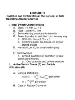
2 General Concept of I> I(DC). b. Buck Case c. Boost Case d. Buck-Boost Case 2. I(critical),Rcritical and Kcritical and their comparision with K(D). 1. Lecture 37. Discontinuous Conduction Mode A. Discontinuous Conduction Mode (DCM). versus Continuous Conduction Mode (CCM): Transitions 1. Review of CCM and Transition to DCM. We show below an UPS converter block diagram to review the basic blocks of a PWM or switch mode converter. 1. UPS (Uninteruptable Power Supply) Converter Block Battery AC Uncontrolled line voltage Filter DC DC-DC DC. Diode DC Load (1-phase or Capacitor (unregulated) Converter (requlated). 3-phase). Rectifier (unregulated). vcontrol Mains Low EMI Feedback Rectifier Highly Stable DC output Consider a converter with operation in a single quadrant of Vo - Io operation at the load.
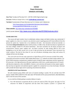
3 The 50-60 Hz mains is converted to DC. The DC acts as a voltage rail for square wave generation at the switch frequency, which is 103 to 104. larger than the mains value. The key to achieving a stable DC output, from the switch mode signal is two-fold. One is the use of an output filter set at near the switch frequency and two the use of feedback to alter the duty cycle of the switches to achieve a controlled DC output. We need to make a careful choice of L and C low pass filter 2. elements at the load to achieve low ripple dc output. PWM Signal Input to LC Filter Low-pass + filter voi iL io Vd Vd +. +. voi R. + vL - C vo=Vo Vo - - (load). - 0 t toff Ts=1/fs The frequency spectrum for a square wave of peak value Voi has a simple Fourier spectrum as shown below in terms of the switching frequency fsw.
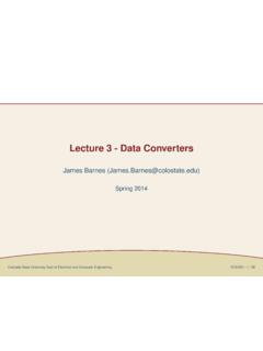
4 We showed previously the Fourier coefficients of the square wave vary as (2 Voi/n )Sin(n /2). We must set the low pass filter to attenuate heavily all signals with f > fsw. Vo 0 f fs 2fs 3fs (=1/Ts). Usually simple two pole filtering fc of a single L-C section allows for a 40 dB/decade drop in signal above the cut-off frequency. 1. fc =. 2 LC. What we will see in CCM to DCM transitions is that the AC. signal into the L-C filter will change wave-shape. Hence, the output DC level is expected to change when this occurs. 3. 20log10|vo/voi|. Vo/voi 0 db -40 db -80 db f fc 10fc 100fc fs (log scale). V o is flat or DC-like below f and rolls off at 40 dB / decade c V oi above fc.
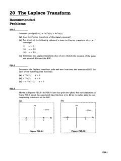
5 Placement of fc compared to fsw is one key decision to be made by the PWM dc-dc converter designer. After the output filter you have an effective DC Vo = M(D)Vin plus the ac ripple. Whose magnitude is set by the filter design. So for a variation of Voi = Vd level we will see at the output a ripple variation in normal CCM operation. vd(t) vd range Vd,min Vo 0. t As we will soon see it is the relative value of the AC ripple, I, compared to the dc levels, I(DC), that is crucial to the transition in circuit conditions from the CCM to the DCM. Usually this occurs at light loads where V(ac) > VDC. Since all switch mode power supplies can be operated open circuit or at light load we have to deal with DCM in a complete power supply design.
6 We cannot avoid DCM of operation. 2. Review of CCM and Transition to DCM. 4. a. Buck and Boost With Unipolar Switches 1. Buck Circuit 2. Boost Circuit 3. Brief Introduction to DCM operation Since both I and I vary with circuit (L,R,Vg)and timing parameters, D, we can set a condition for I> I. In CCM the transistor and diode alternatively conduct and the switching period Ts has only two portions: DTs (transistor-on and 5. diode-off) and D'Ts (diode-on and transistor-off). We thus have two electrical circuits occurring over a switch period. In PWM dc-dc converters we can find load conditions where circuit voltages and currents are zero for a brief time interval.
7 During this unique interval, a new and third circuit topology combination not normally allowed is now possible. This is called the DCM mode and will turn out to be a big practical advantage in several ways. In the DCM. mode the DTs interval is usually unchanged because the transistor conduction is controlled solely by the control signal D, which is independent of circuit operation. However, the D'Ts period is divided by circuit conditions into two new portions, often called D2, and D3. The diode conduction duration depends solely on the circuit conditions which change during the D'Ts interval to shut off the diode prematurely. When turn-off occurs depends on the load conditions.
8 The value of D2 or D3 in DCM operation becomes an additional unknown in addition to D. This division of the D'interval into D2 and a new D3 interval usually happens when I(out) has a minimum DC value called the critical current, Icritical. DCM usually occurs at light load and Vout jumps up from its CCM value, for the buck-boost converter, to a higher value output-voltage as we will see herein. This can be very useful for power supplies employed for starting fluorescent lights, which initially have zero load till gas ignition or breakdown occurs. That is we need an initial large voltage to start the lamp. It could be deleterious for a microprocessor or logic power supply if the over-voltage damages circuits.
9 2. Unidirectional Current Restriction of Solid State Switches will insure DCM of operation. 6. Consider a simple uni-directional current flow diode: i Uni-directional v current in a diode The switch mode circuit conditions alone make the diode to switch on/off in synch with the actively driven transistor. We need no active diode control. However, in some cases shown below the diode is inadvertently shut off when I(load). < IDC(min), regardless of the transistor switch state. This introduces a third circuit condition or state within the switch period, to the two states we have considered so far in CCm operation. This third state will alter both average DC and AC.
10 Properties of the basic converter circuits. Lets look at the Boost circuit as we reduce the DC current level at the load. We still have the case above that the inductor current is positive and flows through the diode during the entire switch period. However, this is precariously depending on the DC. level of the inductor current. What occurs if we reduce the DC current level lower than that shown above?? Can the diode conduct a negative current? What does the negative current do the inductor current waveform. In turn does this create a third circuit condition that we have been droning on about? Lets do this in two steps. First at the edge--- 7. Now over a portion of the switch period the inductor current is zero and the diode is turned off creating a third circuit condition.