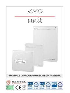
Transcription of BENTEL reserves the right to change the contents of …
1 BENTEL reserves the right to change the contents of this manual without prior notice , via Florida Valtesino - 63013 GROTTAMMARE (AP) - ITALYI nstallation and use manual : FIRE CONTROL PANELS J524-F and BUSQ 050299 INDICE INTRODUCTION5J524-F and J506-F control panels .. 5 Optional items .. 5 Description .. 6 Inputs .. 6 Outputs .. 6 Functioning .. 7 Interface .. 9 Access to signalling and commands .. 10 Power supply .. 10 PARTS IDENTIFICATION11 LED s .. 11 Parts description .. 12 Description of the buttons .. 16 INSTALLATION17 Installation of supplementary boards .. 17 Control panel mounting .. 18 Connections .. 18 Main board and expander board terminals.
2 18 Main board terminals .. 19 Connection example .. 21 Connection of the power supply .. 25 Installation table .. 26 Maintenance .. 26 QUICK GUIDE27 Technical features .. 27 Description of the terminals .. 27 USE29 Fire alarm .. 29 Fault alarm .. 29 Silence .. 29 Disable .. 30 Rearming .. 30 Test .. 30 The display module .. 30 Summary .. 33 GENERAL FEATURESMAIN BOARD 6 CONTROLLED/BYPASSABLE input zones. Up to 21 devices can be connected to each zone: conventional fire detectors, alarm buttonsand gas detectors. One alarm-repeat output for each input zone. NON-CONTROLLED/NON-SILENCEABLE/NON-BYPAS SABLE fire-alarm outputs at24 V plus Free Voltage Exchange.
3 CONTROLLED/SILENCEABLE/BYPASSABLE fire-alarm outputs at 24 V and at 12 V. CONTROLLED/SILENCEABLE/BYPASSABLE fault-warning output at 24 V. Connection terminals for the JS24 annunciator panel. J524-F: connector for the 6 zone JES56-F expander board. J524-F: connector for the serial interface. Visual (LED s) and acoustic (buzzer) function-status signals. J506-F: incorporated power supply/battery-charger V, POWER-SUPPLY Power supply/battery-charger V, BOARD 6 CONTROLLED/BYPASSABLE input zones. Up to 21 devices can be connected to each zone: conventional fire detectors, alarm buttonsand gas detectors. One alarm-repeat output for each input Commands protected by lockable door. Holes for externally laid cable and and chased cable conduit.
4 Removable door. J524-F: supports up to 3 expander boards (24 zones), and display module. J524-F: compartment for two 12 V, 17 Ah : compartment for two 12 V, 7 Ah Control Panels J524-F and J506-F INTRODUCTIONJ524-F and J506-F control panelsThe J5024-F and J506-F control panels have been developed andmanufactured according to the high standards of quality, reliabilityand performance of all BENTEL SECURITY srl parts of the J524-F and J506-F control panels are at their bestwhen the environmental conditions, external to their containers, com-ply with the 3k5 category of the IEC 721-3-3 J524-F and J506-F control panels are basically similar: both have amain board with 6 CONTROLLED/BYPASSABLE input zones.
5 CONTROL-LED/SILENCEABLE/BYPASSABLE fire and fault-alarm outputs, and otheroutputs without these J524-F model is suitable for large installations, it supports up to 3 ex-pander boards for a total of 24 zones, and a display module; it also has anRS232 interface for PC connection, a A switching power-supply, andhouses two 12 V, 17 Ah J506-F model is suitable for medium sized systems, it has a 6 zonemain board, and is powered by an on-board A linear power-supply, andholds two 12 V, 7 Ah models have terminals for the connection of an annuciator itemsJES56-FThis is an expander board with 6 input zones, for the connection of fire de-tectors, and connectors for a main board and other expander boards.
6 Bymeans of these connections, the expander boards communicate the statusof their inputs to the main board, which in turn activates the signalling andcontrol devices. Several expander boards may be connected, thus, permit-ting total customization. JLCD5-FThis is a display module with a backlit LCD, with two rows of 16 characterseach. By means of the 4 buttons under the display, it is possible to obtaindetailed information on the warnings signalled on the LED s on the frontpanel of the J524-F model. Only the J524D-F is equipped with the displaymodule, but it is possible to install the module in the J524-F is a annunciator panel which can be connected, by means of just 5wires, to the J524-F and J506-F control panels.
7 It is for the repetition of allthe visual and acoustic signals, and can be installed up to 100 metresaway from the control panel. SoftwareThe software runs in Windows environment, and controls the status of theJ524-F control panel connected via RS-232 serial to the PC. It also permitscontrol panel programming, event logging and print-out. INTRODUCTION5 DescriptionInputsThe control panel has specified inputs for fire detection devices (detectionzones), for the connection of the conventional fire detectors. These inputsact as open contacts during standby status, and as resistors during alarmstatus. Therefore, devices with the same features as fire detectors, suchas alarm buttons and gas detectors can also be connected.
8 Do not connect more than 21 devices to each are normally-balanced inputs with a 2,700 ohm resistor, and can de-tect and signal fire, lines in short-circuit (possibly generated by detectorfault), and tamper-on-line (caused by the removal of a detector from itsbase).OutputsThe outputs of the J506-F and J524-F control panels can be divided intotwo groups: CONTROLLED/SILENCEABLE and NON-CONTROL- first group (CONTROLLED/SILENCEABLE) consists of: an output with the positive ( V) in the event of an alarm (terminals30-31[AT+]); an output where the positive ( V) fails in the event of an alarm (ter-minal 32[AT-]); an output where the positive ( V) fails in the event of an alarm (ter-minal 34[F]), this is particularly suitable for the connection of telephone di-allers which function at 12 control panel can detect and signal short-circuits and interruption onthese outputs, and has silence buttons to disable them.
9 Silencing effectsonly these outputs, and does not effect NON-CONTROLLED/NON- SI-LENCEABLE [AT+] and [F] outputs comply with the EN54-2 second group (NON-CONTROLLED/NON-SILENCEABLE) consists of: a specific output for the connection of intrinsically safe devices, such asthe self-powered sirens at 24 V (terminal 27[+N]); a specific output for the connection of piezoelectric sirens, fire bells, flash-ers and similar devices which function at 24 V (terminal 26[+A]); a free exchange (terminals 23[NO] 24[COM] and 25[NC]) which, by meansof simple wiring, permits control of all the devices which cannot be con-nected directly to the other two outputs. Only devices which function with SELV current (Safety Extra Low Voltage)can be connected to the NON-CONTROLLED/NON-SILENCEABLE Control Panels J524-F and J506-FA repeat output ([Ox] terminal) is assigned to each input zone, for selectivemanagement in the event of fire, and activates only the devices in thezone which generated the first group (CONTROLLED/SILENCEABLE) has an output that is acti-vated in the event of fault: the negative is on this output (terminal 28[-G])during this the event of alarm on an armed detection zone, the control panel acti-vates the devices connected to the alarm alarm status is indicated.
10 By the solid ALARM LED assigned to the zone that has generated the alarm; by a quick intermittent sound emitted by the control-panel buzzer; by the solid FIRE ALARM LED on the front panel; by the message K6 YbU 1\ 6- ! D 1\ - ! <- ! M on the displayof the J524D-F model (see "Fire alarm" on page 29); by the connected terminals 24[COM] and 23[NO]; by Voltage ( V) on the terminals 26[+A] and 31[+AT+]. by Voltage failure ( V) on the terminal 27[+N] and 32[AT-]; by Voltage failure ( V) on the terminal 35[F]. Press the SILENCE button to stop the silenceable alarm-outputs momen-tarily, this status will be held until the button is pressed the RESET button to stop the alarm cycle assigned to the input zones, and to certain fire and fault-alarmoutputs are CONTROLLED, therefore, in standby status they must be con-nected to ground with a 2,700 ohm resistor (red-purple-red-gold), if how-ever, they are short-circuited or open they will generate a fault alarm, indi-cated: by an intermittent sound ( s) on the control panel buzzer; by the solid SYSTEM FAULT LED on the front panel of the control panel.


