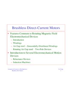
Transcription of BLDC motor control with Hall sensor based on FRDM-KE02Z
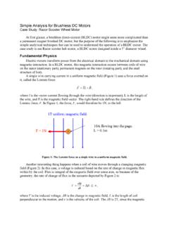
1 1 IntroductionThe speed control circuits of DC motors are simple and easyto use, and hence are very popular in motor speed controlsystems. However, due to the brushes, DC motors suffer froma lower reliability. The brushless DC (BLDC) motor is alsoreferred as an electronically commuted motor . There are nobrushes on the rotor and the commutation is performedelectronically at certain rotor a DC motor with a BLDC motor places higherdemands on a control algorithm and a control circuit. First, the BLDC motor is usually a three-phase system;so, it has to be powered by a three-phase power supply. Second, the rotor position must be known at certainangles in order to align the applied most common way to control a BLDC motor is to useHall sensors to determine the rotor position. The controlsystem senses the rotor position and the proper voltage patternis applied to the application note describes the basic DC and BLDC motortheory and the implementation of the six-step commutationmethod on KE02 sub-family MCUs.
2 KE02 is a 5 V MCU withenhanced FlexTimer(FTM), suitable for BLDC motor SemiconductorDocument Number:AN4776 Application NoteRev 0, 07/2013 BLDC motor control with HallSensors based on FRDM-KE02 Zby:Xianhu Gao 2013 Freescale Semiconductor, theory of motor theory of six-step to control BLDC motor withFRDM-KE02Z .. board and transfer boardKinetis E Series Freedom Development ( FRDM-KE02Z ) board forms the basis of the control system and has the followingfunctions. Supplies PWM control signal to the BLDC board Processes Hall sensor signal and values of bus voltage and currentA transfer board is used to connect the FRDM-KE02Z board and the BLDC drive boardThe BLDC board is APMOTOR56F8000: motor control Demonstration System, powered by 9 V DC. On this board, youcan implement the six-step Hall sensor algorithm and sensorless algorithm.
3 In this application note, Hall sensor is configuredand detail information can be found at: APMOTOR56F8000: motor control Demonstration requirementThe software is based on CodeWarrior ( ) or higher latest version of CodeWarrior is , and can be found at: theory of motor controlThis figure shows the basic principle of nearly all kinds of motor rotations. The rotor and the stator in the motor generate theinteractive force and the rotor spins as long as the force is in the same 1. motor control fundamentalsBasic theory of motor controlBLDC motor control with Hall Sensors based on FRDM-KE02Z , Rev 0, 07/20132 Freescale Semiconductor, motor controlAs seen from Figure 1, the rotor spins in the clockwise direction because the force is in the direction of the rotor , after rotating 180 , the direction of the force changes, preventing the rotor from spinning and trying to drag it last, the rotor will not spin in the same direction but just effective way of keeping the force in the same direction is to change the current direction in the coil at the same timewhen the force direction changes.
4 See this figure. This process is called 2. motor commutationIn the DC motor , the brush commutator is used. See the following 3. Brushed DC motorBasic theory of motor controlBLDC motor control with Hall Sensors based on FRDM-KE02Z , Rev 0, 07/2013 Freescale Semiconductor, the rotor spins to a certain position, the direction of the current in the coil will be changed by the brush, so the rotorwill spin in the same direction forever. However, if the direction of the input current to the brush changes, so will the rotorspin brush commutator has the following advantages. Ease of control Self-commutating Low rotor inertia, coreless rotors Lowest total system cost for basic motion High starting torque and can run with AC or DCHowever it has some many disadvantages as follows.
5 Higher maintenance cost due to brush wear Electrical noise due to mechanical commutation Maximal speed limited by commutator Heat is generated in armature which is difficult to remove because the armature is on the rotor. Friction losses associated with mechanical commutation Not usable in intrinsically safe motor controlA BLDC motor can overcome the shortcomings of the DC motor . The basic structure of BLDC motor is different ascompared to DC motor because it has no mechanical commutator (brush). In a BLDC motor , the coil is wound on the stator,the rotor has surface-mounted permanent magnets, and the brush commutator is replaced with the electronic 4 shows the structure of a three-phase BLDC motor . The external rotor (some motors are internal) has four pole pairsand consists of the permanent magnet.
6 The stator consists of three-phase windings (A, B, and C). Figure 5 is an abstractschematic of the previous stator windings. It is easy and intuitive to analyze magnetic field of the stator using this MCU and the control circuit is the theory of motor controlBLDC motor control with Hall Sensors based on FRDM-KE02Z , Rev 0, 07/20134 Freescale Semiconductor, 4. BLDC motor structureFigure 5. Stator winding connection of a three-phase BLDC motorThe stator windings can generate the magnetic field when powered, which will attract or repel the permanent magnet (rotor),as a result of which the rotor spins. See the following theory of motor controlBLDC motor control with Hall Sensors based on FRDM-KE02Z , Rev 0, 07/2013 Freescale Semiconductor, 6. Internal magnetic forceThe following figure shows how to generate the magnetic field in the stator.
7 Here, the positive current is defined as thecurrent flowing into a specific phase, or coming out of a specific 7. Magnetic field generationSimilar to the DC motor , if the MCU and control circuit in a BLDC motor do not change the direction of the magnetic fieldgenerated by the stator windings in time, the rotor won t spin. In BLDC motor , a rotating magnetic field should be generatedby the windings. Therefore, there must be a way to conform the position of commutation and change the this purpose, the Hall sensor method is discussed in this application theory of six-step commutation methodIf the rotor wants to spin stable clockwise or counterclockwise, an associated rotating magnetic field must be generated fromthe stator windings, which will attract or repel the permanent magnetic (rotor).
8 Magnetic fieldAs shown in Figure 7, each phase of the stator coil can generate the magnetic field in two directions and so, the current andthe rotating magnetic fields in the three-phase coils can be easily controlled. Six patterns of magnetic fields (see the followingfigure) generated are the basis of six-step commutation, which is explained in the following theory of six-step commutation methodBLDC motor control with Hall Sensors based on FRDM-KE02Z , Rev 0, 07/20136 Freescale Semiconductor, 8. Rotating magnetic fieldBasic theory of six-step commutation methodBLDC motor control with Hall Sensors based on FRDM-KE02Z , Rev 0, 07/2013 Freescale Semiconductor, commutationThe Hall effect sensor is a sensing switch that outputs a logic level based on the magnetic field detected. The Hall effectsensors (Ha, Hb, and Hc) are inserted into the example, when the Ha sensor is under the N pole of the permanent magnet, it will output signal 1, otherwise 0.
9 See thefollowing the outputs of all the three sensors will theoretically give 8 status from 000 to 111. However, in most cases,because of the hardware constraint, signal 000 and 111 don t exist. So, the other 6 status can divide the one electrical 360 ofposition into six areas, and the exact point where the status changes from one to another is the position that the commutatorchanges the direction of the stator s magnetic 9. Hall sensor outputFigure 10 depicts an example of commutation where the Hall sensor status is shown to be 010. Now, for the rotor to spinclockwise, the clockwise rotating magnetic field must be generated in its nearest area, that is, where the Hall sensor status is011. This direction of magnetic field can be generated by turning on the coil AC, which means that the current flows into A,and runs out of C.
10 When the rotor runs to the area of 011, the Hall sensor status changes to 011 and at the same time, thecommutator changes from AC to BC, to keep the rotor running after the rotating , the power sequence is AC -> BC -> BA -> CA -> CB -> AB -> is the summary of the commutation process. In one complete rotation of 360 electrical degrees, the excitation of the stator windings will be changed six times, andeach change is called a commutation. The angle between S-N pole (rotor) and magnet field (stator windings) is 60-120 , commutation happens at 60 . The commutation position is when the status of the Hall sensor changes. At every moment, only two phases have current, while the third one is powered theory of six-step commutation methodBLDC motor control with Hall Sensors based on FRDM-KE02Z , Rev 0, 07/20138 Freescale Semiconductor, 10.