Transcription of Bow Window Assembly and Installation Guide
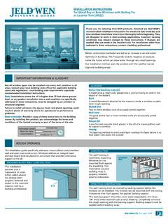
1 Bow Window Assembly and Installation Guide for Andersen Casement windows Thank you for choosing Andersen. Instructions are for typical, new wood-framed wall construction with weather protection in place. Instructions may not be right for all installations due to building design, construction materials or methods used and/or building or site conditions. Consult a contractor or architect for recommendations. Flanges on the unit alone will not properly flash and seal the Window . Follow these instructions carefully. For questions call 1-888-888-7020 Monday - Friday, 7 to 7 and Saturday, 8 to 4 central time. For more information and/or guides visit Please leave this Guide with building owner. Read Guide from beginning to end before starting Installation . Read all warnings and cautions during unit Installation . Use caution when working at elevated Follow manufacturers' instructions for hand windows and doors can be heavy.
2 Use safe heights and around unit openings. Follow or power tools. Always wear safety glasses. lifting techniques and a reasonable number manufacturers' instructions for ladders and/or Failure to do so may result in injury and/or of people with enough strength to lift, carry scaffolding. Failure to do so may result in injury product damage. and install Window and door products to or death. avoid injury and/or product damage. Unless specifically ordered, Andersen windows Andersen Head Flashing and Installation Flanges DO NOT take the place of standard Window and doors are not equipped with safety glass, and door flashing. Unit must be properly flashed and sealed with sealant for protection and if broken, could fragment causing injury. against water and air infiltration. Use non-reflective flashings. Highly reflective flashing tapes Many laws and building codes require safety can raise the surface temperature of the vinyl to the point where vinyl deformation and product glass in locations adjacent to or near doors.
3 Damage may occur. Andersen windows are available with safety Do not apply any type of film to glass. Thermal stress conditions resulting in glass damage glass that may reduce the likelihood of injury could occur. when broken. Information on safety glass is available from your local Andersen dealer. Use of movable insulating materials such as Window coverings, shutters, and other shading devices may damage glass and/or vinyl. In addition, excessive condensation may result causing deterioration of windows and doors. Andersen and all other marks where denoted are trademarks of Andersen Corporation. 2003-2010 Andersen Corporation. All rights reser ved. 0002062 BC Revised 03/03/10. Section One - Bow Window Assembly Guide Component Identification Extension Jamb Upper/Lower Platforms Extension Jamb Side Head/Seat Boards Side Flashing Flashing Casement Casement Unit Unit 10 Mullion Post 10 Mullion Post Outside 10 Outside 10.
4 Mullion Post Trim Interior Sides Up Mullion Post Trim Parts Included Tools and Supplies 10 Mullion Posts Safety Glasses Small Pry Bar Outside 10 Mullion Post Trim Strip Hammer 2" x 4" Skid Material Interior 10 Mullion Post Trim Level 1" x 4" Cross Bracing Perma-Shield Casement/Awning windows Carpenters Square Soft Rags Upper/Lower Platforms Combination Square Jack and Support Head/Seat Boards* Tape Measure Shims and Blocks Side Flashing Clamps Power Screw Gun Cable Support System Drill/Driver Flat Head Wood Screws 3/8" Drill Bit #10 x 2-1/4". Optional Accessories 1/8" Drill Bit #8 x 1-1/2". Extension Jambs Awl #8 x 2-1/2". Auxiliary Casing Utility Knife #8 x 3". Head Flashing Pencil 1-1/2" (4d) Nails Head and Seat Board Inside Trim Caulk Gun Miter Saw Fibrex Cellular Trim Board Sealant Isopropyl Alcohol * Head and Seat Boards may not be required for walkout installations.
5 Metal fasteners and other hardware components may corrode when exposed to preservative treated and fire-retardant treated lumber. Obtain and use the appropriate metal fasteners and hardware as called out by the Installation Guide to fasten unit to any rough opening made from pressure treated and fire-retardant treated lumber. Failure to use the appropriate materials for the Installation may cause a failure resulting in injury, property or product damage. 2. Section One - Bow Window Assembly Guide Section One - 10 Bow Window Assembly Guide for Andersen Casement windows Side 1. Unit Preparation Side Head Jamb Jamb Wall must be 4-9/16' to 7-1/8" for stock platforms, head boards, and seat boards. Exterior Side Up Carefully remove units from cartons and place exterior side up on a clean flat work surface. Remove foam packing blocks. Using a sharp utility knife, remove Installation Flanges from Sill vertical sides only of all units.
6 Cut off flush with Side Jamb. Side Installation Side Installation Flanges (removed) Flanges (removed). 2. Remove Inside Stops Head Stop Side Stop on lock side of tandem lock Casement Units Side Stop (remove first). has an underlying lock mechanism. Use caution when (remove removing Side Stop on lock side to avoid damage to second). lock mechanism and/or Side Stop. Turn units interior side up. Carefully remove all Inside Stop nails with a hammer and block of wood. Sill Stop Side Stop (remove first) (remove Remove the Head and Sill Inside Stops before Side Stops. second). Insert a small pry bar between frame and Side Stops and gently pry outwards. Bundle Inside Stops and place in protected area until reinstallation. Interior Side Up 3. Arrange Units and 10 Mullion Posts for Assembly When arranging units for Assembly , make sure placement and direction of venting units are correct.
7 Stationary units must be installed with Installation arrow on label pointing up towards head of unit. Arrange units and 10 Mullion Posts in position for Assembly . Unit Unit Unit Unit Head 10 Mullion Post 10 Mullion Post Sill Unit Five-Wide Unit shown in illustration. 10 Mullion Post 10 Mullion Post Interior Side Up 3. Section One - Bow Window Assembly Guide 4. Join and Secure Units and 10 Mullion Posts 10 Mullion Choose two units and one 10 Mullion Post. #10 x 2-1/4" Post #10 x 2-1/4". Screw Screw Place support blocks under Flanker Units to align with 10 Mullion Post. Position 10 Mullion Post flush with top and bottom of Interior, Side Interior Side units. Jamb Kerf Jamb Kerf Clamp units and 10 Mullion Post in position. Secure units to 10 Mullion Post with #10 x 2-1/4". screws every 6" to 8". Locate screws in Side Jamb where shown. Repeat above steps for all Window units and 10 Mullion Post until Bow Unit is complete.
8 Side Jambs Interior Side Up Flanker Unit Unit Flanker Unit 10 Mullion Post #10 x 2-1/4" 10 Mullion Post Screw Clamps Clamps 10 Mullion Post 10 Mullion Post Unit with 10 Mullion Support Blocks Support Blocks Posts Attached Completed Unit 5-Wide Unit shown in illustration. Follow the same Assembly procedure for 2-Wide, 3-Wide, 4-Wide, 6-Wide, and 7-Wide Units. 4. Section One - Bow Window Assembly Guide 5. Prepare Platforms Platform Carpenters Square Interior Edge (rough side). Place Platforms rough side up on work surface. Measure length of Platform along interior edge. Place Pencil pencil mark at center of Platform. Mark centerline across width of Platform using carpenters square. Centerline Mark Repeat step for other Platform. Flip Platforms over, smooth side up (opposite side of Pencil centerline mark). Scribe a line 2-1/4" in from, and along entire length of exterior edge of Platforms, using combination square.
9 2-1/4". Platform Scribed Line (smooth side). Combination Square 6. Mark Centerline on Unit Mark Center Here Head Number of Window units will determine centerline placement on Bow Unit. Follow procedure below according to number of units being joined. 3-Wide, 5-Wide, and 7-Wide Units Measure width of center unit along frame. Place pencil, mark at center of unit on frame. Sill Repeat step at other end of center unit. 3-Wide, 5-Wide, and 7-Wide Units 4-Wide and 6-Wide Units Mark Center Here Interior Side Up Head Place a pencil mark in center of middle Mullion Post. Repeat step at other end of middle Mullion Post. Mullion Post Sill 4-Wide and 6-Wide Units 5. Section One - Bow Window Assembly Guide 7. Position Platforms Position Platform, centerline facing inward, on end of Bow Lower Platform Unit and up against Installation Flanges. Align centerline of Platform with Centerline Scribed Line center mark on Bow Assembly .
10 Fasten Platform to ends of Center Upper Platform Unit (or units) along scribed line Head using two #8 x 1-1/2" flathead wood screws. Repeat above step for other Platform. Sill Upper Platform (in position). Head Installation Flanges Lower Platform (in position). Sill Scribed Line #8 x 1-1/2" Screws Interior Side Up 8. Position Head and Seat Boards*. Seat Board*. Head and Seat Boards (unfinished side). are temporarily installed as templates to assist in securing platforms to Head Board*. Window units. (finished side). Seat Board Head Board Determine interior finished (in position) (in position). Clamp Head Clamp side of Seat Board. Place Seat Board, finished side toward interior, into position against Lower Platform. Clamp Center Seat Board to obtain Lower Platform best fit. Clamp Seat Board to Lower Platform. Sill Interior Side Up Repeat step to Head Board and Upper Platform.