Transcription of bq24259 I2C Controlled 2A Single Cell USB Charger ...
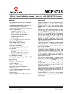
1 VBUSPMIDSDASCLINTOTGCEPSELSWBTSTREGNPGND SYSBATILIMTSSYS: USBSDP/DCPT hermal PadREGN1 F! ! F!1 H!10!F317W( max) F!10 F! Enable (0 C - 45 C) bq24259 Copyright 2016, Texas Instruments IncorporatedProductFolderSample &BuyTechnicalDocumentsTools &SoftwareSupport &CommunityAn IMPORTANTNOTICEat the end of this datasheetaddressesavailability,warranty, changes,use in safety-criticalapplications,intellectual propertymattersand NOVEMBER2015 REVISEDSEPTEMBER2016bq24259I2C Controlled2A SingleCell USB ChargerWith NarrowVDCP owerPath Managementand AdjustableVoltageUSB OTG1 Features11 90%HighEfficiencySwitchMode2-A Charger Inputvoltageand currentlimit and InputCurrentLimit.
2 100 mA, 150 mA, 500 mA,900 mA, 1 A, A, 2 A USBOTG with to Vat 1 A or A FastOTGS tartup(22 ms Typical) 90%5-V BoostModeEfficiency Accurate 15%HiccupModeOvercurrentProtection NarrowVDC(NVDC)PowerPathManagement InstantSystemOn with No Batteryor DeeplyDischargedBattery IdealDiodeOperationin BatterySupplementMode Low Inductor I2C port for optimalsystemperformanceandstatusreporti ng AutonomousBatteryChargingwith or withoutHostManagement BatteryChargeEnable BatteryChargePreconditioning ChargeTerminationand Recharge HighAccuracy 7% ChargeCurrentRegulation 3% OutputVoltageRegulationin USBOTGB oostMode HighIntegration PowerPathManagement
3 SynchronousSwitchingMOSFETs IntegratedCurrentSensing BootstrapDiode InternalLoopCompensation Safety BatteryTemperatureSensingfor ChargingandDischargingin OTGMode BatteryChargingSafetyTimer ThermalRegulationand ThermalShutdown Inputand SystemOver-VoltageProtection MOSFETOver-CurrentProtection ChargeStatusOutputsfor LEDor HostProcessor Maximumpowertrackingcapabilityby inputvoltageregulation 20- A Low BatteryLeakageCurrentand SupportShippingMode 4-mmx 4-mmVQFN-24 Package2 Applications TabletPC, SmartPhone,InternetDevices PortableAudioSpeaker3 DescriptionThebq24259is a highly-integratedswitch-modebatterycharg emanagementand systempowerpathmanagementdevicefor 1 cell Li-Ionand Li-polymerbatteryin a widerangeof smartphoneand low impedancepowerpathoptimizesswitch-modeop erationefficiency, serialinterfacewithchargingandsystemsett ingsmakesthe deviceatruly (1)PARTNUMBERPACKAGEBODYSIZE(NOM) bq24259 VQFN(24) x (1)
4 For all availablepackages,see the orderableaddendumatthe end of the ,ChargingfromSDP/DCP,andOptionalBATFETE nableInterface2bq24259 SLUSCF0B NOVEMBER2015 : bq24259 SubmitDocumentationFeedbackCopyright 2015 2016,TexasInstrumentsIncorporatedTableof Contents1 Description(Continued)..36 Pin Configurationand Applicationand Deviceand Mechanical,Packaging,and RevisionHistoryChangesfromRevisionA (January2016)to RevisionBPage Changedpin 21 of thePinFunctionstableFrom:"anodeof the boost-strapdiode.
5 " To: "cathodeof the boost-strapdiode." ..5 Changedpin 22 of thePinFunctionstableFrom:cathodeof the boost-strapdiode." To: "anodeof the boost-strapdiode." ..5 ChangedVREFTo: VREGNin Figure17, Figure18, and Equation1 ..21 Changedthe RESET valueof Bit 3 and Bit 2 From:1 To: 0 in Table10 ..32 Changedthe RESET valueof Bit 2 From:0 To: 1 and Bit 1 From:1 To: 0 in Table11 ..32 AddedNote1 to Figure39 ..36 Changed"between15 kHz and 25 kHz" To: "between15 kHz and 36 kHz" in the last paragraphof (November2015)to RevisionAPage Changedpin "BOOT" To: "BTST" in the Changedpin "BOOT" To: "BTST" in Figure39.
6 NOVEMBER2015 REVISEDSEPTEMBER2016 ProductFolderLinks: bq24259 SubmitDocumentationFeedbackCopyright 2015 2016,TexasInstrumentsIncorporated5 Description(Continued)The V V USBinputsources,includingstandardUSBhost port and USBchargingportwith V and powerspecificationswith inputcurrentand set the defaultinputcurrentlimit,the bq24259takesthe resultfromthedetectioncircuitin the system,suchas devicealso supportsUSBOn-the-Gooperationbyproviding fast startupand V (default5 V) on the VBUS withanaccuratecurrentlimit up to powerpathmanagementregulatesthe systemslightlyabovebatteryvoltagebut doesnot Vminimumsystemvoltage(programmable).
7 Withthis feature,the systemkeepsoperatingevenwhenthe batteryis completelydepletedor inputsourcecurrentor voltagelimit is reached,the powerpathmanagementautomaticallyreducest he chargecurrentto zeroand thenstartsdischargesthe batteryuntilthesystempowerrequirementis deviceinitiatesand completesa chargingcyclewhenhostcontrolis not automaticallychargesthe batteryin threephases:pre-conditioning,constantcur rentand the end,the chargerautomaticallyterminateswhenthe chargecurrentis belowa presetlimit in the ,whenthe batteryvoltagefalls belowthe rechargethreshold,the chargerwill chargedeviceprovidesvarioussafetyfeature sfor batterychargingand systemoperation,includingnegativethermis tormonitoring,chargingsafetytimerand over- thermalregulationreduceschargecurrentwhe nthe junctiontemperatureexceeds120 C (programmable).
8 The STAT outputreportsthe chargingstatusand any INT immediatelynotifieshostwhenfault bq24259is availablein a 24-pin,4 x 4 mm2thin 12 VBUSPSELPGILIMTSQONCE4bq24259 SLUSCF0B NOVEMBER2015 : bq24259 SubmitDocumentationFeedbackCopyright 2015 2016,TexasInstrumentsIncorporated6 Pin Configurationand FunctionsRGEP ackage24-PinVQFNWithExposedThermalPad(To pView)Pin FunctionsPINTYPEDESCRIPTIONNAMENUMBERVBU S1, internaln-channelreverseblockMOSFET(RBFE T)is connectedbetweenVBUSandPMID with VBUSon 1- F ceramiccapacitorfromVBUSto PGNDand placeit as closeas possibleto USBhost sourceand Low indicatesan the pull up rail via 10-k goodinputsourceif the inputvoltageis betweenUVLOand ACOV,aboveSLEEP modethreshold,and currentlimit isabove30 the pull up rail via 10-k fault conditionoccurs,STATpin in the chargeblinksat 1 the logicrail througha 10-k the logicrail througha 10-k INT to a logicrail via 10-k INT pin sendsactivelow.
9 256- spulseto host to reportchargerdevicestatusand selectionpin duringbuckmode,and activehigh enablepin bq24259 ,whenin buckmodewith USBhost (PSEL= High),whenOTG= High,IINlimit = 500 mA and whenOTG= Low,IINlimit = 100 boostmodeis activatedwhenthe REG01[5]= 1 and OTGpin is ChargeEnablepin. Batterychargingis enabledwhenREG01[5:4]= 01 and CE pin = pin mustbe pulledhigh or sets the maximuminputcurrentlimit by regulatingthe ILIM voltageat 1 V. A resistoris connectedfromILIMpin to groundto set the maximumlimit as IINMAX= (1V/RILIM) KILIM.
10 The actualinputcurrentlimit is the lowerone set by ILIMand by I2C REG00[2:0].The minimuminputcurrentprogrammedon ILIMpin is 500 a resistordividerfromREGNto TS to BoostdisablewhenTSpin is out of 103AT-2thermistoris logiclow to high transitionon this pin with minimum2ms high levelturnson BATFETto exit has internal1M (Typ)pull backwardcompatibility,whenBATFET enablecontrolfunctionis not used,the pin can be a no connector tied to TS pin (10kNTCthermistoronly).(RefertoShippingM odefor detaildescription).