Transcription of Build a 2-Meter Intermod Notch Trap - N5DUX
1 -- -- -- -- --- - -- - - - - --A CQ VH F Project - - - - Build a 2-Meter Intermod Notch Trap Bothered by Intermod from high-powered pagers? Trap their signals before they reach your receiver with this Build -it-yourself Notch filter. By Jim Ford, N6JF" ? f you've heard a grumbling tone on 1 I your 2-Meter rig, chances are you've I! become a victim of paging Intermod . In case you haven't noticed, pagers have become a ubiquitous consumer device. Since they're very small and normally sit next to your body, they have very ineffi- cient antennas. The paging companies make up for this with lots of transmit power and many transmitter sites. Herein lies the problem for hams: their frequen- cy band is close to our 2-Meter band (roughly MHz for the Southern California area). The effects of Intermod , or Intermod - ulation distortion, are heard when two or more strong off-the-air signals create additional signals inside your receiver.
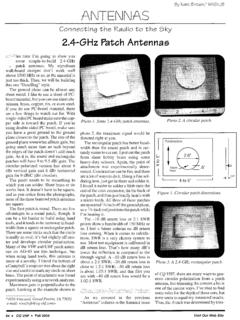
2 The fact that these additional signals are not really there is little comfort to the per- son receiving the interference. What causes the "phantom" signals is non lin- earity of the receiver itself. All receivers have it to some extent, but some are more prone to problems than others. There are three common methods of reducing Intermod problems. 1. Strengthen receiver front end (RF stage, mixer, and IF) 2. Add a bandpass filter 3. Add a Notch filter Let's briefly look at each of these, start- ing with the front end. Receivers today are often designed The author with the coinpleted 2-Meter helical rzotchfilter. Tuned to MHz, it "notches o~tt" iiztegereizce from nearby pager transmit- ters. (Photos by Gordon West, WB6 NOA) with more emphasis on price than on big signal performance. For example, many receivers use dual gate MOSFET transis- tors as first mixers.
3 These transistors are good considering their price, but are not so good when encountering big signals such as the pagers. A more expensive but "bulletproof' mixer is a diode double-balanced mixer. These are immune to interference, but they have loss instead of gain and require much more local oscillator power to drive "Jim Ford, N6JF, is a digital and RF designer and a college electronics in- structor. He is also a regular contributor to a variety of radio publications. "Since [pagers are] very small and normally sit next to your body, they have very inefficient antennas. The paging companies make up for this with lots of transmit power and many transmitter sites. Herein lies the problem for hams .." them. This requires two additional ampli- fier stages, one to make up for the lost gain in the mixer and the second to ampli- fy the local oscillator signal.
4 This, of course, raises the price. Finally, IF (inter- mediate frequency) amplifiers that are designed for big signals are generally cur- rent hogs with more power supply drain than other devices, and perhaps even require a small heat sink. Good RF front end design can reduce both in-band (144 to 148 MHz) and out-of-band Intermod . But receiver front end redesign is a major project, and not our emphasis here. Bandpass filters are a good way to reduce Intermod caused by out-of-band signals (for more on bandpassfilteus, see "Sniffing Out 'Birdies' on Your Radio," CQ VHF, September, ). But the most common paging frequencies are just slightly out-of-band, in percentage terms, to 2 meters . A bandpass filter will have to work hard to eliminate the pag- ing signals. Getting the necessary level of rejection often requires more than one stage-and that, again, means a greater expense.
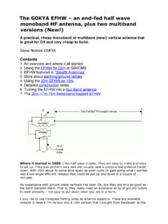
5 To its credit, a bandpass filter will reduce interference caused by any- 32 CQ VHF June 1997 Ham Radio Above 50 MHz "A Notch filter blocks all signals from a narrow frequency band. It does not need to be bypassed when listening outside the 2-Meter band (unless you like to listen to pager signals)." dle the power of a 50-watt transceiver, on the form. It's easy to stretch the coil then read on-this project's for you. to the right length but harder to get good form if you have to squeeze the loops " " :,\ ST * \ <.# tcz:;! back together. The coupling loop is 1-l/2 turns close er is a wound on a 5/8-inch form. It should be resonatorhookedup as a "suck-out parallel to the larger coil, but shouldn't with a tuned coupling loop as an input/ touch it, and in the same plane as the con- Top view of the$lter. Note that there is no Output. The design uses a 2-inch copper nectors.
6 The smaller coil should be cen- top connection for the helical coil. Solder water pipe many tered in the tube and wound in the same blob indicated is the connection point for the plumbing supply houses. It should be direction (clockwise, for example) as the bottom end of the coil. See text for attach- inches long (being off by a '110 of coil for maximum coupling. ment details. an inch should cause no problems). I had ~h, 15-pF capacitor is soldered direct- to buy aminimumlengthof l2 inches for ly between one of the connectors and the thing outside of the band, including mixer Just under $10, but it Was good to have l-l/2-turn coupling loop. I didn't like an extra pipe, since I tried two versions of unsupported connection at the coil, but images. But that also means you'll need this project. to bypass it if you want to listen to any- thought more hardware in the RF field thing outside the 2-Meter band, such as While a hacksaw I got a inside of the tube would create more much leaner cut by remarking the problems than it would solve.
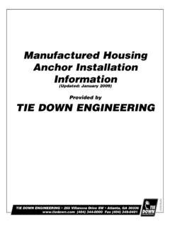
7 Aircraft or weather. And, generally speak- length and having the local plumbing ing, the bandpass filter needed to elimi- supply house cut it for me with its large nate paging from a 2-Meter re- tubing cutter. They charged me $2 for this ceiver will have more loss than another service, You,ll also need: ,%,">7 r,q/s, *>=-(F ",,C< alternative, which is the focus of this arti- Three feet of bare copper wire for -. ~22 .#-I -2 cle. Enter .. the Notch filter. the coil. Actually, this is enough for two I found that a regu1ar coils in case you make a mistake. nected to the copper tube with two brass . ~b~~~ 6 inches of#12 enameled wire nuts and screws, was the easiest approach for the coupling loop. you can use the to connecting the coax. The start of the wire for this as well, but it's harder helical coil and both connectors are .625 The final common method of reducing to work with.)
8 Inch from the bottom of the tube (see paging interference is a Notch filter. A . A loop tuning capacitor. I used a 15 Figure). I used a 5/8-inch chassis punch Notch filter blocks all signals from a nar- p~, 100-volt disc ceramic (~i~i-~~~ part to make the connector holes on my sec- row frequency band. It does not need to number 1328~~). A silver mica or a chip ond version. The chassis punch slightly be bypassed when listening outside the 2- capacitor should work at least as well. flattens the copper tube, but that isn't a meter band (unless you like to listen to . some sort offeedline connector (two problem. The connectors should be pager signals). And a Notch filter gener- .fthem), ~h~ type you use is your choice, mounted directly opposite each other. ally has less loss than a bandpass filter. but I used two SO-~39~. The flange on the SO-239 should be The only disadvantage is that it elimi- mounted on the outside of the tube be- nates interference from only a very nar- cause, otherwise, the connector would row group of frequencies.
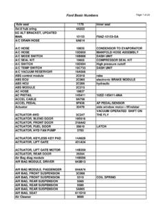
9 Is this a prob- protrude too far into tube and interfere lem? Only if your interference comes The helical coil should be inches in with the helical coil. In fact, you'll still from a variety of sources on many dif- diameter, inches long, and about need to file off about half of the connec- ferent frequencies. turns. I say about turns because tor pin to avoid being too close to the heli- One of the ads from a Notch filter man- it will vary according to your exact diam- cal coil, but there will be enough pin left ufacturer states that 99% of Intermod eter, pitch, and centering in the tube. I'd to make a solder connection. comes from the paging frequencies. I start with turns and a length of 1'.66 In addition to the holes for the connec- don't know if this is true for everyone, inches, then tune it by cutting the top with tors, you'll need to drill a 7/64-inch hole but I know that paging transmitters cause stout wire cutters (more on this later).
10 I about 3/4 of an inch away from one of the the majority of my Intermod problems. used apiece of 3/4-inch Schedule 40 PVC connectors (technically, it shouldbemea- I recently had a chance to test a band- tubing as a form to wind the coil. It has a sured in degrees, but this is close enough). pass filter by DCI and a Notch filter by diameter of inches, and the coil This is where you'll connect the helical Par Electronics. Both of these products diameter was just right after I removed coil. The #10 wire is almost exactly ,100 are excellent, and I'd recommend them the PVC. If you don't have a inch in diameter, so the nearest fraction- wholeheartedly. However, if you want to form, then use a l-inch form with two or al drill bit for the hole is 7/64, which is brew your own Notch filter that has very three turns of black tape on it. Wind the.