Transcription of CABINET UNIT HEATER SUBMITTAL DATA - mesteksa.com
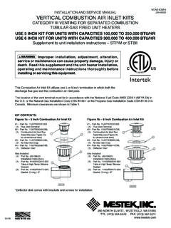
1 CABINET unit HEATER SUBMITTAL DATAR ecessed Wall Mounted Units - Models RW and RWIPIPING AND MOUNTING CONNECTIONS SHOWN ARE TYPICAL FOR ALL AIR FLOW ARRANGEMENTS SEE OTHER :_____LOCATION:_____ARCHITECT:_____ENGIN EER:_____CONTRACTOR:_____PO NUMBER:_____DATE:_____260 NORTH ELM STREET / WESTFIELD, MA 01085 TEL: (413) 568-9571 FAX: (413) R SIZE0203040608101214PC1297 2PC1297 3PC1297 4PC1297 6PC1297 8PC1297 10PC1297 12PC1297 1415/32" x 8 11/16" x 19 3/4"15/32" x 8 11/16" x 27 3/4"15/32" x 8 11/16" x 31 3/4"15/32" x 8 11/16" x 43 3/4"15/32" x 8 11/16" x 45 3/4"15/32" x 8 11/16" x 50 3/4"15/32" x 8 11/16" x 57 3/4"15/32" x 8 11/16" x 69 3/4"FILTER IDENTIFICATION AND DATARWIRWIRECESSED WALLRECESSED WALLINVERTED FLOWCABINET unit HEATERSSHIPPING WEIGHT(LBS)
2 STYLE 02 03 04 06 08 10 12 14 RW 97 115 128 157 175 185 207 234 / 7 DIRECT105087512309851/102115/1 / 7 DIRECT1050875141011301/102115/1 CAP. - HOTWATERMBH20 WTDGPMHIGH CAP. - COIL 2 ROWHEATING WATERGPM20 CAP. - STEAM2 PSIG MBHSTANDARDEDRCOILCOND. LB/HRCOIL:NUMBER FINS PER INCHFACE AREA-FT2 COIL CONNECTIONSBLOWERS: NUMBERDIAMETER/WIDTHDRIVERPM -HILOWCFM:HIGHLOWMOTOR: - LEVEL 18" FROMUNITLENGTHHEIGHTDEPTHUNIT SIZEENTERING WATER - 200 ENTERING AIR - 60 TABLE I03040608101214 CABINET unit HEATERSRATINGS AND / 7 DIRECT10508752301851/151115/1 / 7 DIRECT10508753352701/151115/1 / 7 DIRECT105087510608451 @ 1/101 @ 1/152115/1 / 7 DIRECT10508758606851 @ 1/101 @ 1/152115/1 / 7 DIRECT10508756305051/101115/1 / 7 DIRECT10508754303451/101115/1 RWI-1130 DIM L SIZE020304060810121435"43"47"59"61"66"73 "85"ENTERING WATER - 200 F ENTERING AIR - 60 FTABLE 1 unit SIZE0203040608101214 Heating Cap.
3 - HotWater WTD Cap. - Coil 2 RowHeating Water WTDH eating Cap. - Steam2 PSIG EDR94131171276313356434451 Coil Cond. :Number Fins Per Inch1212121212121212 Face Connections1-1/4CU1-1/4CU1-1/4CU1-1/4CU1 -1/4CU1-1/4CU1-1/4CU1-1/4 CUBlowers:Number11223344 Diameter/Width (In)5-3/4 x 75-3/4 x 75-3/4 x 75-3/4 x 75-3/4 x 75-3/4 x 75-3/4 x 75-3/4 x 7 Standard PSC Motor:HP1/151/151/101/101 @ 1/10 1 @ 1/10 1/101/101 @ 1/151 @ 1/15 RPM: High10501050105010501050105010501050 Low875875875875875875875875 Number 11112222 Volts/Phase/Hertz 115/1/60115/1/60115/1/60115/1/60115/1/60 115/1/60115/1/60115/1/60 Amperes Speed ControlStandard : High230335430630860106012301410 Low1852703455056858459851130 Optional ECM Motor.
4 HP1/151/151/151/151/101/101/41/4 Number 11112222 Volts/Phase/Hertz 120/1/60120/1/60120/1/60120/1/60120/1/60 120/1/60120/1/60120/1/60 Amperes Speed ControlECM Mtr3 - SPEED3 - SPEED3 - SPEED3 - SPEED3 - SPEED3 - SPEED3 - SPEED3 - SPEEDCFM: High230335430630860106012301410 Med160240375440590740850980 Low120150280320450560640730 Filter: (In)19-3/427-3/431-3/443-3/445-3/450-3/4 57-3/469-3/4 Width (In)8-11/168-11/168-11/168-11/168-11/168 -11/168-11/168-11/16 Thickness (In)1/21/21/21/21/21/21/21/2dB. Level 18" From Unit5052535455555656 Length (In) 3543475961667385 Height (In)2525252525252525 Depth (In)9-1/29-1/29-1/29-1/29-1/29-1/29-1/29 -1 FAN SPEEDUNITSIZEGPMHIGH FAN SPEEDMBHWTDFATCFMMBHWTD FAT0203040608101214185270345505685845985 1130 CFM1191291351401461251281291311321111241 2913313612513313614014211712312512612911 5118120121124131133134135136114116117119 120 CABINET unit HEATERSHEATING WATER - 200 FENTERING AIR - 60 FTABLE II STANDARD WATER - 200 FENTERING AIR - 60 FAN SPEEDUNITSIZEGPMHIGH FAN SPEEDMBHWTDFATCFMMBHWTD III HIGH CAPACITY 2 ROW COILCABINET unit HEATERSHEATING FAN SPEEDUNIT SIZEGPMHIGH FAN SPEEDMBHWTDFATCFMMBHWTD FAT0203040608101214185270345505685845985 1130 CFM1241291351401461251281291311321111241 2913313612513313614014211712312512612911 5118120121124131133134135136114116117119 120230335430630860106012301410 FAN SPEEDUNIT
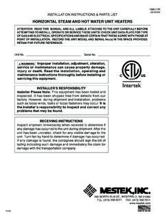
5 SIZEGPMHIGH FAN SPEEDMBHWTDFATCFMMBHWTD & WARRANTY* 260 NORTH ELM STREET / WESTFIELD, MA 01085 TEL: (413) 568-9571 FAX: (413) *STANDARD CABINET unit ONLY The contractor shall furnish and install Sterling CABINET unit heaters as selected to meet or exceed job requirements. The Cabi-net unit heaters will conform to the items listed below and be certified under CSA All cabinets will be constructed with 18-gauge cold rolled steel, side panels and top. The front panel shall be furnished in 16-gauge cold rolled steel. It will have 1/2", 1-1/2 pound insulation with one side neoprene coated in front of coil. The internal CABINET shall be furnished in 18-gauge galvanized steel. Adequate work area for installation of control valves or electrical equipment shall be provided on both sides of the internal CABINET .
6 The CABINET shall be provided with a neutral eggshell baked enamel prime coat as standard. (Available if specified) Powder coated baked enamel, color selected from standard. All cabinets shall be supplied with adjustable rear mounting brackets which will provide adjustment to correct alignment of the unit at installation to non square or out of true walls, joists, studs or surfaces. Adjustable leveling legs (two each base leg) are available when specified. RECESSED UNITS All recessed units shall be supplied with a "Wall Seal" assembly. This assembly shall provide protection to the wall or ceiling construction material. The "Wall Seal" shall be supplied in an eggshell baked enamel prime coat as standard. (When specified) Baked enamel colors may be selected from MOUNT OR RECESSED UNITS All "C" and "RC" units shalll be supplied with a hinged front panel.
7 The multiple hinges shall provide full swing through 90 . A safety chain shall be provided as standard to prevent the face panel from swinging fully open accidentally. This chain must be easily detached to allow full access for servicing. Speed control switch will be shipped with wiring diagram for installation where All filters supplied as standard shall be reusable aluminum media with a 69% arrestance level. Filters shall be slide in type which are locked into position with a cotter pin. FANS Fan wheels shall be centrifugal, forward curved, double width of electro galvanneal steel. Fan housings shall be of formed galva-nized sheet STANDARD ONE ROW - The durable mechanically bonded copper/aluminum coil presents the best of today s hydronic heating technology. All element assemblies are submersion tested at factory at 250 PSI and are rated at a working pressure of 300 PSI.
8 All units are designed so that field modifications can be made to reverse the coil position if required. HIGH CAPACITY COIL - This is a hot water coil designed to provide increased capacity when the required load exceeds that of the standard coil for a given size. Its construction is similar to the standard coil however, there are two rows of tubes. Element assemblies are submersion tested at 250 PSI and are rated at a working pressure of 300 Standard PSC motors shall have integral thermal protection and start at 78% of rated voltage. Optional PSC High Static motors will be capable of operating in high static conditions up inches of water column. All motors shall be factory run-tested and assembled in unit prior to shipping. Optional ECM and high static motors will have a solid state control board and a 3 speed switch.
9 All motors shall be factory run-tested and assembled in unit prior to shipping. ELECTRICAL All primary internal wiring shall be done at the factory and every unit shall be factory tested for AIR DAMPERS ON DESIGANTED UNITS ONLY When desired specify either of the following: 1 . Where noted 25% Manual Outside Air Dampers shall be provided. A manually operated damper quadrant shall provide from 0% to 25% outside air through the use of a single blade damper. 2. Where noted 25% Motorized Outside Air Dampers shall be provided. A synchronous motor (115/60/1) interlocked with the blower shall automatically open the outside air damper when blower starts. The single blade damper shall be adjustable from 0% to 25% outside air. When the blower stops or there is a loss of power, the damper shall return to the closed position.
10 A damper override switch shall be provided to prevent damper operation when The products in this catalog are warranted by Sterling, to be free from defects in material and workmanship for a period of one (1) year from the date of shipment from Sterling's plant. Sterling's liability under this warranty is limited to replacing or repairing at our option, our plant any defective component or assembly returned to our factory prepaid and with proper return authorization document. All repairs or replacements are made subject to factory inspection. In the interest of product improvement, Sterling reserves the right to make changes without notification.