Transcription of Cadence Tutorial B: Layout, DRC, Extraction, and LVS
1 Cadence Tutorial B: layout , DRC, extraction , and lvs Created for the MSU vlsi program by Professor A. Mason and the AMSaC lab group. Document Contents Introduction Create layout Cellview Design Rule Checking layout Parameter extraction layout vs. Schematic Comparison Introduction This document is one of a three-part Tutorial for using Cadence Custom IC Design Tools (ver: IC445) for a typical bottom-up digital circuit design flow with the AMI06 process technology and NCSU design kit. This Tutorial demonstrates how to complete the physical design ( layout ), design rule check (DRC), parameter extraction , and layout vs. schematic (LVS) using the Cadence tools. These operations are performed step-by-step to complete the design of an inverter cell, began in Tutorial A, using the design rules for the AMI C5N ( = ) fabrication process.
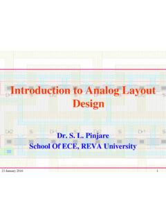
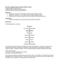
2 Techniques and tips for using Cadence layout tools are presented. It is important that you always have a verified functional schematic before beginning layout . If the schematic is not correct, the layout will also be incorrect. As shown in the figure below, the layout should contain the same pin names and the transistors must be made the same size as those in the schematic. In this Tutorial the nMOS and pMOS transistors both use the minimum size transistor dimensions (W = and L = ) for the AMI C5N process. Design rule illustrations for the AMI C5N process can be found at: Create layout Cellview The custom design process is discussed briefly in Tutorial A. We will assume that you have logged on and started Cadence Design Tools, and that you already have created a design library and the schematic of the inverter.
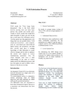
3 Please refer to Tutorial A if you have not done so. Cadence Tutorial B: layout , DRC, extraction , and lvs 1 STEP 1: Create a new layout view From the Library Manager window, Select File => New => Cellview. A dialog box will appear prompting you for the library, cell, and view names. Make sure that the library name corresponds to your design library that you have used in Tutorial A. Enter inv as the Cell Name and choose Virtuoso as the Design Tool. The View Name will be automatically set to layout . Two design windows (Virtuoso and LSW) will pop-up. The Layer Selection window (LSW) (small window on the left in the figure below) lets the user select different layers of the mask layout .
4 Virtuoso will always use the layer selected in the LSW for editing. The LSW can also be used to determine which layers will be visible and which layers will be selectable. To select a layer, simply click on the desired layer within the LSW. Virtuoso is the main layout editor of Cadence design tools. Commonly used functions can be accessed by pressing the buttons/icons of the toolbar on the left side of this window. There is an information line at the top of the window which shows (from left to right) the X and Y coordinates of the cursor, number of selected objects, the distance traveled in the X and Y directions, the total distance, and the command currently in use.
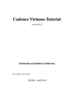
5 This information can be very handy while editing. At the bottom of the window, another line shows the function of each mouse button. Note that the mouse button functions will change according to the command you are currently executing. The default mouse mode is selection, and as long as you do not choose a new mode you will remain in that mode. To quit from any mode or command and return to the default selection mode, the ESC key can be used. STEP 2: Display Setup Before drawing on a new cell you should always setup the grid properties. In the Virtuoso layout Editing window, select Options => Display (or type e ) to bring up the Display Options window shown below. Cadence Tutorial B: layout , DRC, extraction , and lvs 2 Type in the following settings: Minor Spacing , Major Spacing , X Snap Spacing , Y Snap Spacing , then click OK.
6 It is also very important to note that the grid spacing is in micrometers (um) and not in lambda ( ). STEP 3: Creating VDD (Power) and GND Rails Now we are ready to start laying out our design. The first parts we will create are the power and ground rails for our inverter. Usually a circuit will consist of a large number of cells, all of which need power and ground connections. Therefore it is common to design cells with the same spacing between the power and ground so that they can easily be connected together when the cells are placed side by side. This vertical spacing is called the cell pitch and it is generally standardized for all cells in the same library to facilitate combining cells in higher-level circuits.
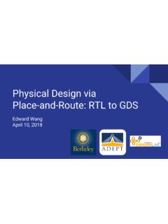
7 For this Tutorial the power and ground rails will be made 3um (10 lambda) wide using the Metal-1 layer and the standard cell pitch (height from bottom of the GND rail to top of the VDD rail) will be 21um (70 lambda). Now draw the Power Rail and the Ground Rail in Metal-1 as shown below. Select metal1 dg layer from the LSW. In the rest of the Tutorial , always use the dg layers for your layouts unless otherwise specified. In the Virtuoso layout Editing window click Create => Rectangle (or select the create rectangle tool from the toolbar). Move your mouse to the cell origin, where the horizontal and vertical guidelines intersect. Check the information bar at the top of the screen to make sure you are at the right location (0,0).
8 Click on this point. Move the mouse up and right to create a rectangle. Use the data in the information bar to move your mouse to the point that is horizontal and 3um vertical from the origin ( x 3 um is always in the X direction by the Y direction, respectively). Click on this point to create the Metal-1 rectangle which will be your ground rail. Repeat these steps to draw the VDD rail 21um (70 lambda), top to bottom, above the GND rail. Read the Useful Editing Tools section below. Cadence Tutorial B: layout , DRC, extraction , and lvs 3 Useful Editing Tools Ruler: The ruler is very useful to place objects and measure the distance between the objects. To start the ruler, click on the ruler icon at the bottom of the toolbar (shortcut key is k ).
9 Click the start and end point in the window; a ruler is created showing the distance between the two points. Hit the ESC key to exit the ruler command. To remove all ruler markers on your layout , press Shift+k . Move: If you place the objects on the wrong place, you can use move function to adjust the location of the object. Select Edit => Move (or click on the move icon on the toolbar), (shortcut key is m ). A window will pop-up. The Snap Mode is an interesting option. When this is in orthogonal setting, the copied objects will move only along one axis. This is a good feature to help you avoid alignment problems. When you have finished the move operation, hit the ESC key to exit the move command.
10 Copy: If you want to create the same object repeatedly, you can use the copy function. Select Edit => Copy and the copy dialog box will pop-up (shortcut key is c ). Click in an object. Notice that an outline of the object will attach to your mouse cursor. Move our mouse and click when you are satisfied with the location to place a copy of the object. Cadence Tutorial B: layout , DRC, extraction , and lvs 4 Delete: If you want to delete an object you have drawn: Place your mouse over the object and left-click to select it. Press the Delete key on the keyboard. Undo: When you make a mistake (accidentally delete a component, etc.), you can undo the action by click on the Undo icon in the toolbar (shortcut key is u ).