Transcription of Physical Design via Place-and-Route: RTL to GDS
1 1 Physical Design via place -and- route : RTL to GDSE dward WangApril 10, 20182 RTL Stands for Register Transfer Level An abstraction for digital circuits, consisting of Combinational logic Registers (state elements) Modules (hierarchical and blackbox - analog macros, SRAM macros, etc) and ports/nets Described in terms of a hardware description language (HDL)3 Hardware description languages (HDLs) An HDL is a language for describing circuits using the RTL abstraction. Includes facilities for describing combinational logic, registers/state, and modules. Common HDLs: Verilog, VHDL. Research-y HDLs: FIRRTL, add_one : input clock : Clock input reset : UInt<1> output io : {flip in : UInt<4>, out : UInt<4>} <= tail(add( , UInt<1>("h01")), 1)4circuit HelperDelayedAdd2 : module HelperDelayedAdd2 :input clock : Clockinput reset : UInt<1>output io : {flip in : UInt<4>, out : UInt<4>} reg my_reg : UInt, clockmy_reg <= tail(add( , UInt<1>("h01")), 1) <= tail(add(my_reg, UInt<1>("h01")), 1)RTL in Action (FIRRTL)Module/port description(Combinational) logicRegisters/state5module HelperDelayedAdd2 ( input clock, input reset, input [3:0] in, output [3:0] out); reg [3:0] my_reg.
2 Always @ (posedge clock) begin my_reg <= in + 4 h1; end assign out = my_reg + 4 h1;endmoduleRTL in Action (Verilog)Module/port description(Combinational) logicRegisters/state67 Digression: HDL vs HCL Chisel (strictly speaking) isn t an What s the difference?sourcesourceHDLHCL8 PyMTL Bluespec Magma Lava Netlist etcOther HCLs/HDLs9 RTL Design Is Only Part of the Picture10 RTL Design Is Only Part of the Picture11 What Makes Creating Hardware Difficult? What makes the Design cycle long and expensive? Architectural Design Space Exploration RTL Development [J. Bachrach et al, DAC 2012] Physical Design and Implementation Verification - is it correct?
3 Validation - is it the right problem to solve? Compilers and Generators Having reliable, re-usable, and robust tools is the name of the game BAG, Chisel, Physical Design MattersPhysical Design is HARD - CAD Tools Aren t AutomaticCAD Tools Which logic gates do I need? Can you try to place them in this way? Where did the logic gates end up? Verilog InstancesTCL ScriptsChipLegendsource codegenerated fileAgile RTL is slowed by non-Agile Physical DesignChisel + FIRRTLRTL GeneratorVerilog InstancesChipsTCL ScriptsCAD Tools16 Digression: Why Agile Physical Design ? (AMS) Usability for Faster Design Space Design17 Research Plug18 Physical Design is a collection of many difficult problems No silver bullet Need to lower barrier to solving these problems Other tapeouts solve these problems, but their solutions are not general or reusable Get designers to encode solutions in a more reusable way, so future tapeouts can leverage previous work (even with different technologies, CAD tools, or designs) Provide collection of API s that designers leverage to build these tools Higher-level and CAD-tool independent directives Directly manipulate/introspect on RTL Higher-level technology abstractionsHAMMER/CICL.
4 A Modular Platform to Encode Expertise and Intent19 What HAMMER means for this of other research tapeouts flow to reduce the complexity of VLSI flows and make them more designer knowledge/expertise in a robust s a ton of info that ends up in people s heads as you do stuff, and it s hard to write stuff down in a productive pain for future tapeout students like yourselves20 Big Picture Overview (Simplified)ChiselFIRRTLV erilogGDSF loorplanTCLT iming & I/O ConstraintsSRAMs FIRRTLM acroCompilerPDK and Standard Cell LibrarySRAM CacheAnalog MacrosNote: in real life chips need to go on boards with packages, StrategyPhysical Design21 Chisel -> FIRRTL Recap: Chisel is a HCL embedded in Scala That is to say - every Chisel Design is a Scala program, which when executed, emits a concrete instance of a circuit in FIRRTL.
5 We are using digital top ( place and route tool will manage the top level), so we will instantiate analog macros in the digital top. A brief note on scan chains: we will use a scan chain generator written in Chisel22 MacroCompiler In Chisel, we specify memories using an abstract Mem()/SyncReadMem() construct:class SRAMTest extends Module { val io = IO(new Bundle {val in = Input(UInt( ))val en = Input(Bool())val out = Output(UInt( )) }) val counter = Counter(1024) val mem = SyncReadMem(1024, UInt( )) when ( ) { ( , ) () } := ( )}23 MacroCompilercircuit HelperSRAMTest : module HelperSRAMTest : input clock : Clock input reset : UInt<1> output io : {flip in : UInt<32>, flip en : UInt<1>, out : UInt<32>} reg value : UInt<10>, clock with.
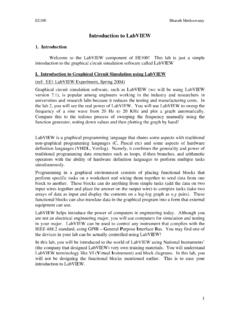
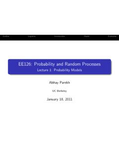
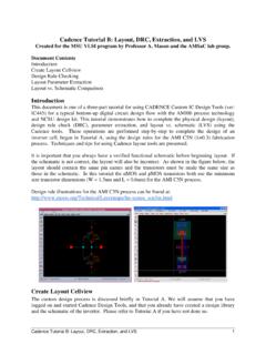
6 (reset => (reset, UInt<10>("h00")) smem mem : UInt<32>[1024] when : write mport _T_10 = mem[bits( , 9, 0)], clock [..] node _T_16 = bits( , 9, 0) read mport _T_17 = mem[_T_16], clock <= _T_17 What it looks like in Verilog ( giant bank of flip flops):reg [31:0] mem [0:1023];24 MacroCompiler However, by default, these memories would compile to standard cell flip-flops, which is very area-inefficient for implementing memories in contrast to SRAM macros. Example:SRAM macro implementationFlip-flop implementation25 MacroCompiler Solution: FIRRTL compiler passes that identify the generic memories from Chisel/FIRRTL (ReplSeqMem) and replace them with modules which use collections of BlackBox SRAM memories (MacroCompiler) given a cache of technology SRAMs.)
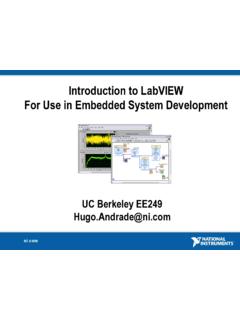
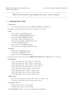
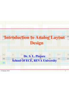
7 ReplSeqMem: Replace mem => mem_ext (create blackboxes) MacroCompiler: Create the mem_ext module which uses technology SRAMs26 Timing and I/O Constraints Clock constraints - tells the tool about clock frequencies, uncertainty/jitter, etc. Can also specify related clocks I/O constraints - specifies input and output delays, capacitances for external pins I/O types/cells - specifies I/O types (input, output, tri-state) and corresponding cells to drive pins27 Bumps vs Wirebond Pads Bumps: metal ( Cu) bumps on top of the chip which we flip over and bond to a substrate/board Wirebond pads: wires are used to bond exposed metal on top of the chip to a substrate/package/board In this class, we will use wirebond padssourcesource28 False Paths False paths A logically impossible path that appears with a naive analysis.
8 Look at the timing report and declare it as a false path. Dangerous if misusedsource29 Synthesis Maps RTL (Verilog) to a post-synthesis netlist (structural Verilog). Standard cells come in different sizes and drive strengths. The synthesis tool uses the previously-mentioned constraints to select standard cells appropriately. Synthesis will also perform optimizations to simplify the RTL. if all of a module s inputs are constants, it may optimize away the module entirely by precomputing its cell libraryConstraintsSynthesis30 Synthesis Examplemodule adder (input [1:0] a,input [1:0] b,output [1:0] c);assign c = a + b;endmodulemodule adder(a, b, c); input [1:0] a, b; output [1:0] c; wire [1:0] a, b; wire [1:0] c; wire n_0, n_1, n_3, n_4, n_5, n_6; NAND2X54_P0 g80__7837(.)
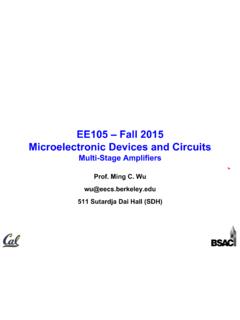
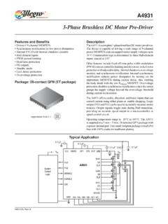
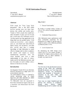
9 A (n_6), .B (n_5), .Z (c[1])); NAND2X3_P0 g81__7557(.A (n_3), .B (n_4), .Z (n_6)); OR2X8_P0 g82__7654(.A (n_4), .B (n_3), .Z (n_5)); NAND2X54_P0 g84__8867(.A (n_0), .B (n_1), .Z (c[0])); XNOR2X6_P0 g83__1377(.A (b[1]), .B (a[1]), .Z (n_3)); NAND2AX3_P0 g86__3717(.A (a[0]), .B (b[0]), .Z (n_1)); NAND2AX3_P0 g85__4599(.A (b[0]), .B (a[0]), .Z (n_0)); AND2X8_P0 g87__3779(.A (b[0]), .B (a[0]), .Z (n_4));endmodule31 Floorplanning Recall: RTL says what to put (logic, state, macros) but doesn t say where to put stuff Floorplanning is the art of specifying placement constraints. Main types of placement constraints: Chip size - tells the place and route tool how large the chip is and how much padding there is Module placement - tells the place and route tools to put cells from a certain module within a certain boundary Macro placement - tells the place and route tool where to put macros ( analog blocks, SRAMs, etc)32 Standard Cell layout Digital layout typically uses standard cells (as opposed to fully custom layouts in analog).
10 Standard cells are transistor-level implementations of CMOS logic gates. Typical structure of a standard cell includes power/ground rails and Cell layout Standard cells are assembled into layouts in tracks by placing them next to each other. Signals are routed in layers above the standard cells. Power is routed to the rails (vdd and gnd) via a power plan ( power grid and vias). Each row is typically mirrored (vdd->gnd, gnd->vdd, etc) Overlap rails, not abut themsource34 Other Aspects of Floorplanning Power planning - defines the power strategy for the chip. For example, a power plan for the chip can involve creating grids for VDD and GND on each layer.