Transcription of Calculating the Total R-Value
1 Case Study Commonwealth of Australia and the States and Territories of Australia 2021, published by the Australian Building Codes material in this publication is licensed under a Creative Commons Attribution International licence, with the exception of third party materials and any trade marks. It is provided for general information only and without warranties of any kind. More information on this CC BY licence is set out at the Creative Commons Website. For information regarding this publication, see case study shows how to calculate the Total R-Value for a Class 6 shop with an external wall system consisting of solid concrete wall with a steel wall frame, in a climate zone 3 location.
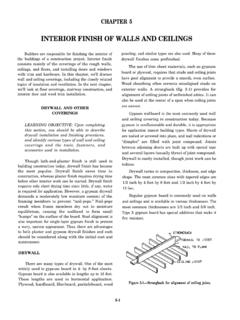
2 The case study shows how to calculate the Total System R-Value , including thermal breaks, in accordance with the Thermal construction Deemed-to-Satisfy (DTS) Provisions in NCC Volume One Section J Energy plasterboardBulk insulationAir spaceSteel framePliable buildingmembraneFigure 1 Illustration of a wall system with solid concrete exterior and steel wall frameScenarioA Class 6 shop is located in climate zone 3. A wall component consists of 100 mm solid concrete, a 62 mm ventilated, non reflective air space, a pliable building membrane, 90 mm thick bulk insulation with a nominal R-Value of ( ), and 13 mm thick gypsum plasterboard .
3 The insulation layer sits within a steel frame and is bridged by the 92 x x mm steel framing studs at 600 mm centres, central noggings, wall tracks and head tracks. The wall is 3 m tall. Figure 1 illustrates this wall material and layer propertiesTable 1 below outlines the construction material and layer properties in this abovementioned wall system. Known properties include thickness, thermal conductivity and the Total R-ValueSolid concrete on a steel framed 1 Construction material and layer properties (From the outside (top of the table) to the inside (bottom of the table))LayerMaterialThickness (mm)Thermal conductivityW ( ) ( ) WExterior surface resistance Air films moving air (assuming wind speed of greater than 3 m/s and not more than 7 m/s) 1 Solid 2 Pliable building membrane<1negligiblenegligibleLayer 3 Ventilated1, non-reflective air 3 (continued)Steel framing 3 (continued)Bulk 4 Gypsum surface resistance Air films still.
4 1 This air space is considered slightly ventilated, so its R-Value is based on a derating of the resistance of an unventilated cavity by a factor of as per the requirements of NZS 4214. Other thermal conductivity and R-Values are as per NCC Specification or for specific products, from manufacturer and supplier data. Layer 3 is the thermal R-Value calculationThis method of Calculating Total R-Value is as outlined in New Zealand Standard (NZS) 4214 Methods of determining the Total thermal resistance of parts of buildings . In general, the R-Value of a material is determined by dividing the thickness of the material (in metres) by the thermal conductivity (in ).
5 The Total R-Value is the sum of the thermal resistance of each layer, surface air film, and any bridged the information provided in Table 1, we know the thicknesses, thermal conductivity, and R-Values, of the individual materials and layers involved in this wall system. Now, let s look at their individual resistance surface air film resistance ( R-Value )R = 1 - 100 mm concrete resistance ( R-Value )As the air space adjacent to the concrete is ventilated, the thermal resistance of the concrete shall be derated by a factor of as per NZS = ( x ) = 2 Pliable building membrane resistance ( R-Value )The pliable building membrane is applied to the outside of the building frame for consistency with common practice to reduce the risk of condensation forming inside the building frame.
6 As the pliable building membrane is less than 1 mm in thickness, the R-Value is considered negligible in this case 3 Air space, insulation and steel Calculating the thermal bridge resistance ( R-Value )Layer 3 consists of a ventilated air space and insulation that is bridged by a steel frame. As per NZS 4214, a bridged layer is never bounded by an air space (including when a membrane is place); therefore, the airspace is included within the thermally bridged layer. However, as the air space is ventilated, its resistance is derated by 45% before being combined with the bridged layer. Layer 3 is split into regions so that each region has only one set of stacked layers within it.
7 There are two regions within Layer 3. Region 1 contains an air space layer and a bulk insulation layer. Region 2 contains an air space layer and a steel frame layer. Figure 2 illustrates the bridged layer regions in this case s go through the steps of Calculating the overall thermal resistance of this layer taking into account the thermal bridge effect of the steel mm air space90 mm bulk insulation60 mm air space92 mm steel frameRegion 1 Region 2 Figure 2 Bridged layer regionsNote: 2 For users of the ABCB Fa ade Calculator, it is not recommended that pliable membranes be included in a wall build up as they have negligible thermal overall rate of heat transfer through the bridged layer is proportional the area-weighted average of the heat transfer rate through each region.
8 In steps 1 and 2, we calculate the thermal resistance and the area of each region, which together determine the rate of heat transfer through each region. In step 3, we calculate the Total thermal resistance of the bridged layer, which is just the inverse of the overall rate of heat transfer through the 1 Calculate the thermal resistance of each region (using the R-Values in Table 1).Region 1 (R1) - insulation R1 = ( (ventilated and non-reflective air space (derated) + (insulation))Region 2 (R2) steel frameTo determine the thermal resistance of the steel frame (Rs), the steel frame can be transformed into an equivalent rectangular shape (see Figure 3)92 mm 13 mm 90 mm mm 60 mm92 mm Figure 3 Equivalent rectangular steel frame transformationThe modified thermal resistance calculated as per equation 9 of NZS 4214, shown below.)
9 Rs=a 1+Rc1 + Rc2d kmWhere: Rs is the steel frame thermal resistance (m .K/W) a is flange width (m) l is the Total thickness (depth) (m) d is the web thickness (m) km is the thermal conductivity of metal (W/m/K) Rc1 is the contact resistance between the steel frame and the plasterboard lining (m .K/W). Rc2 is the contact resistance between the steel frame and the pliable insulation membrane (m .K/W) Rc1 and Rc2 are the contact resistances between metal frame and adjacent facing due to imperfect contact between them. Rc1 is assumed to be (NZS 4214 specifies a value of usually less than , which is equivalent to a gap of about 1 mm).
10 Rc2 assumed to be the dimensions for this configuration (described in the introduction):Rs= + + , we can calculate the R-Value for Region 2: R2 = + = 2 Next, the area fraction for each region is calculated. The area fraction is the ratio of the cross-section area, at right angles to the direction of heat flow, occupied by each region. For this case study, one repeated section of the wall will be examined to determine the fraction of each region in the layer as per Figure 4 below. =+3000 mm600 mmfraction of region 2fraction of region 1 Figure 4 Area fractionsRegion 1 area fractionf1 (region 1) = Cross section area of region 1 Total cross section areaf1 = (600 3000)-((3000 )+( ) 3)600 3000f1 = 2 area fractionf2 (region 2)Cross section area of region 2 Total cross section areaf2 = (3000 )+(( ) 3)600 3000f2 = given there are only 2 regions:f2 = 1 f1f2 = 1 = the Total thermal resistance ( Total R-Value )You can now calculate the Total thermal resistance ( Total R-Value ).