Transcription of CAT34C02 - 2 kb I2C EEPROM for DDR2 DIMM …
1 Semiconductor Components Industries, LLC, 2011 March, 2011 Rev. 171 Publication Order Number: CAT34C02 /DCAT34C022 kb I2C EEPROM for ddr2 dimm serial PresenceDetectDescriptionThe CAT34C02 is a 2 kb serial CMOS EEPROM , internallyorganized as 16 pages of 16 bytes each, for a total of 256 bytes of 8 features a 16 byte page write buffer and supports both theStandard (100 kHz) as well as Fast (400 kHz) I2C operations can be inhibited by taking the WP pin High (thisprotects the entire memory) or by setting an internal Write Protect flagvia Software command (this protects the lower half of the memory).In addition to Permanent Software Write Protection, theCAT34C02 also features JEDEC compatible Reversible SoftwareWrite Protection for ddr2 serial presence detect (SPD)applications operating over the V to V supply voltage CAT34C02 is fully backwards compatible with earlierDDR1 SPD applications operating over the V to V supplyvoltage Supports Standard and Fast I2C Protocol V to V Supply Voltage Range 16 Byte Page Write Buffer Hardware Write Protection for Entire Memory Software Write Protection for Lower 128 Bytes Schmitt Triggers and Noise Suppression Filters on I2C Bus Inputs(SCL and SDA)
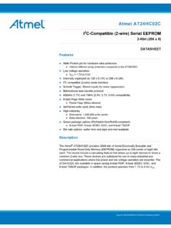
2 Low power CMOS Technology 1,000,000 Program/Erase Cycles 100 Year Data Retention Industrial Temperature Range This Device is Pb Free, Halogen Free/BFR Free and RoHSCompliant*Figure 1. Functional SymbolSDASCLWPCAT34C02 VCCVSSA2, A1, A0*For additional information on our Pb Free strategy and soldering details, pleasedownload the ON Semiconductor Soldering and Mounting TechniquesReference Manual, CONFIGURATIONSDAWPVCCVSSA2A1A01 See detailed ordering and shipping information in the packagedimensions section on page 14 of this data INFORMATIONSCLTSSOP (Y), TDFN (VP2),UDFN (HU3), UDFN (HU4)UDFN 8HU3 SUFFIXCASE 517 AXTSSOP 8Y SUFFIXCASE 948 ALDevice Address InputA0, A1, A2 serial Data Input/OutputSDAS erial Clock InputSCLW rite Protect InputWPPower SupplyVCCG roundVSSF unctionPin NamePIN FUNCTIONFor the location of Pin 1, please consult thecorresponding package 8VP2 SUFFIXCASE 511 AKUDFN 8 EPHU4 SUFFIXCASE 517 AZCAT34C02 1.
3 ABSOLUTE MAXIMUM RATINGSP arameterRatingUnitOperating Temperature 45 to +130 CStorage Temperature 65 to +150 CVoltage on Any Pin with Respect to Ground (Note 1) to + on Pin A0 with Respect to Ground to + exceeding Maximum Ratings may damage the device. Maximum Ratings are stress ratings only. Functional operation above theRecommended Operating Conditions is not implied. Extended exposure to stresses above the Recommended Operating Conditions may affectdevice The DC input voltage on any pin should not be lower than V or higher than VCC + V. During transitions, the voltage on any pin mayundershoot to no less than V or overshoot to no more than VCC + V, for periods of less than 20 2. RELIABILITY CHARACTERISTICS (Note 2)SymbolParameterMinUnitsNEND (Note 3)Endurance1,000,000 Program/ Erase CyclesTDRData Retention100 Years2.
4 These parameters are tested initially and after a design or process change that affects the parameter according to appropriate AEC Q100and JEDEC test Page Mode, VCC = 5 V, 25 CTable 3. OPERATING CHARACTERISTICS (VCC = V to V, TA = 40 C to +85 C, unless otherwise specified.)SymbolParameterTest ConditionsMinMaxUnitsICCS upply CurrentVCC < V, fSCL = 100 kHz1mAVCC > V, fSCL = 400 kHz2 ISBS tandby CurrentAll I/O Pins at GND or VCCTA = 40 C to +85 CVCC V1mATA = 40 C to +85 CVCC > V3 ILI/O Pin LeakagePin at GND or VCC2mAVILI nput Low Voltage x VCCVVIHI nput High x VCCVCC + Low VoltageVCC > V, IOL = 3 < V, IOL = 1 4. PIN IMPEDANCE CHARACTERISTICS (VCC = V to V, TA = 40 C to +85 C, unless otherwise specified.)
5 SymbolParameterConditionsMaxUnitsCIN (Note 4)SDA I/O Pin CapacitanceVIN = 0 V, f = MHz, VCC = V8pFOther Input Pins6 IWP (Note 5)WP Input CurrentVIN < VIH, VCC = V130mAVIN < VIH, VCC = V120 VIN < VIH, VCC = V80 VIN > VIH2IA (Note 5)Address Input Current(A0, A1, A2)Product Rev HVIN < VIH, VCC = V50mAVIN < VIH, VCC = V35 VIN < VIH, VCC = V25 VIN > VIH24. These parameters are tested initially and after a design or process change that affects the parameter according to appropriate AEC Q100and JEDEC test When not driven, the WP, A0, A1 and A2 pins are pulled down to GND internally. For improved noise immunity, the internal pull-down isrelatively strong; therefore the external driver must be able to supply the pull-down current when attempting to drive the input HIGH.
6 Toconserve power, as the input level exceeds the trip point of the CMOS input buffer (~ x VCC), the strong pull-down reverts to a weak 5. CHARACTERISTICS (VCC = V to V, TA = 40 C to +85 C) (Note 6)SymbolParameterStandardFastUnitsMinMax MinMaxFSCLC lock Frequency100400kHztHD:STASTART Condition Hold Period of SCL Period of SCL :STASTART Condition Setup :DATData Hold Time00mstSU:DATData Setup Time250100nstR (Note 7)SDA and SCL Rise Time1000300nstF (Note 7)SDA and SCL Fall Time300300nstSU:STOSTOP Condition Setup Free Time Between STOP and Low to SDA Data Out Hold Time100100nsTi (Note 7)Noise Pulse Filtered at SCL and SDA Inputs100100nstSU:WPWP Setup Time00mstHD:WPWP Hold Cycle Time55mstPU (Notes 7 & 8)Power up to Ready Mode11ms6.
7 Test conditions according to Test Conditions Tested initially and after a design or process change that affects this tPU is the delay between the time VCC is stable and the device is ready to accept 6. THERMAL CHARACTERISTICS (Air velocity = 0 m/s, 4 layers PCB) (Notes 9 and 10)Part NumberPackageqJAqJCUnitsCAT34C02 YTSSOP6437 C/WCAT34C02VP2 TDFN9215 C/WCAT34C02HU3 UDFN10118 C/WCAT34C02HU4 UDFN10118 C/W9. TJ = TA + PD * qJA, where: TJ is the Junction Temperature, TA the Ambient Temperature, PD the Power : CAT34C02VP2, VCC = V, ICCmax = 1 mA, TA = 85 C: TJ = 85 C + 3 mW * 92 C/W = TJ = TC + PD * qJC, where: TC is the Case Temperature, 7. TEST CONDITIONSI nput VCC to VCCI nput Rise and Fall Times 50 nsInput Reference VCC, VCCO utput Reference VCCO utput LoadCurrent Source: IOL = 3 mA (VCC V); IOL = 1 mA (VCC < V).
8 CL = 100 pFCAT34C02 On Reset (POR)The CAT34C02 incorporates Power On Reset (POR)circuitry which protects the internal logic against poweringup in the wrong CAT34C02 will power up into Standby mode afterVCC exceeds the POR trigger level and will power down intoReset mode when VCC drops below the POR trigger bi directional POR feature protects the device against brown out failure following a temporary loss of DescriptionSCL: The serial Clock input pin accepts the serial Clockgenerated by the : The serial Data I/O pin receives input data andtransmits data stored in EEPROM . In transmit mode, this pinis open drain. Data is acquired on the positive edge, and isdelivered on the negative edge of , A1 and A2: The Address pins accept the device pins have on chip pull down : The Write Protect input pin inhibits all writeoperations, when pulled HIGH.
9 This pin has an on chippull down DescriptionThe CAT34C02 supports the Inter Integrated Circuit(I2C) Bus data transmission protocol, which defines a devicethat sends data to the bus as a transmitter and a devicereceiving data as a receiver. Data flow is controlled by aMaster device, which generates the serial clock and allSTART and STOP conditions. The CAT34C02 acts as aSlave device. Master and Slave alternate as eithertransmitter or receiver. Up to 8 devices may be connected tothe bus as determined by the device address inputs A0, A1,and Bus ProtocolThe I2C bus consists of two wires , SCL and SDA. Thetwo wires are connected to the VCC supply via pull upresistors.
10 Master and Slave devices connect to the 2 wirebus via their respective SCL and SDA pins. The transmittingdevice pulls down the SDA line to transmit a 0 andreleases it to transmit a 1 .Data transfer may be initiated only when the bus is notbusy (see Characteristics).During data transfer, the SDA line must remain stablewhile the SCL line is HIGH. An SDA transition while SCLis HIGH will be interpreted as a START or STOP condition(Figure 2).StartThe START condition precedes all commands. It consistsof a HIGH to LOW transition on SDA while SCL is START acts as a wake up call to all receivers. Absenta START, a Slave will not respond to STOP condition completes all commands. It consistsof a LOW to HIGH transition on SDA while SCL is STOP starts the internal Write cycle (when following aWrite command) or sends the Slave into standby mode(when following a Read command).