Transcription of I2C-Compatible (2-wire) Serial EEPROM
1 Atmel-8700H-SEEPROM-AT24C01C-02C-Datashe et_122016 Features Low-voltage Operation VCC = to Internally Organized as 128 x 8 (1K) or 256 x 8 (2K) I2C compatible (2- wire ) Serial Interface Schmitt Trigger, Filtered Inputs for Noise Suppression Bidirectional Data Transfer Protocol 400kHz ( ) and 1 MHz ( , , ) Compatibility Write Protect Pin for Hardware Data Protection 8-byte Page Write Mode Partial Page Writes Allowed Self-timed Write Cycle (5ms max) High-reliability Endurance: 1,000,000 Write Cycles Data Retention: 100 Years Green Package Options (Pb/Halide-free/RoHS-compliant) 8-lead PDIP, 8-lead JEDEC SOIC, 8-lead TSSOP, 8-pad UDFN, 5-lead SOT23, and 8-ball VFBGA Die Sale Options: Wafer Form and Tape and Reel AvailableDescriptionThe Atmel AT24C01C/02C provides 1024/2048-bits of Serial Electrically Erasable and Programmable Read-Only Memory ( EEPROM ) organized as 128/256 words of eight bits each.
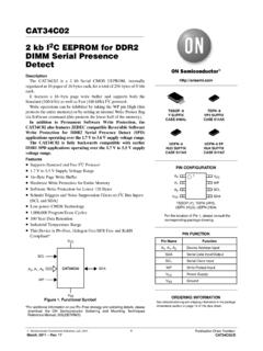
2 Both devices include a cascading feature that allows up to eight devices to share a common 2- wire bus. These devices are optimized for use in many industrial and commercial applications where low power and low voltage operation are essential. The AT24C01C/02C are available in space saving 8-lead PDIP, 8-lead JEDEC SOIC, 8-lead TSSOP, 8-lead UDFN, 5-lead SOT23, and 8-ball VFBGA packages. In addition, the entire family operates from to and AT24C02CI2C- compatible (2- wire ) Serial EEPROM1-Kbit (128 x 8), 2-Kbit (256 x 8)DATASHEETAT24C01C/02C [DATASHEET]Atmel-8700H-SEEPROM-AT24C01C- 02C-Datasheet_122016 Configurations and PinoutsTable Descriptions use of 5-lead SOT23, the software A2, A1, and A0 bits in the device address word must be set to zero to properly NumberPin SymbolPin Name and Functional DescriptionAsserted StatePin Type1, 2, 3A0 A2 Address Inputs: The A2, A1, and A0 pins are device address inputs that are hard wired.
3 As many as eight 1-Kbit or 2-Kbit devices may be addressed on a single bus system. Input4 GNDG round: The ground reference for the power supply. GND should be connected to the system ground. Power5 SDAS erial Data: The SDA pin is bidirectional for Serial data transfer. This pin is open drain driven and may be wire -ORed with any number of other open drain or open collector devices. Input/Output6 SCLS erial Clock Input: The SCL input is used to positive edge clock data into each EEPROM device and negative edge clock data out of each device. Input7 WPWrite Protect: Provides hardware data protection. The Write Protect pin allows normal read/write operations when connected to Ground (GND). When the Write Protect pin is connected to VCC, the write protection feature is enabled and operates as shown in Table Power Supply: The VCC pin is used to supply the source voltage to the device.
4 Operations at invalid VCC voltages may produce spurious results and should not be attempted. PowerNote: Package drawings are not to View876512348-pad UDFNA0A1A2 GNDVCCWPSCLSDAVCCWPSCLSDAA0A1A2 GND123487658-ball VFBGATop View8-lead TSSOPTop View12348765A0A1A2 GNDVCCWPSCLSDATop ViewSCLGNDSDAWPVCC5-lead SOT231235 4A0A1A2 GNDVCCWPSCLSDA8-lead SOICTop View87651234 Top View8-lead PDIPA0A1A2 GNDVCCWPSCLSDA87651234 3AT24C01C/02C [DATASHEET] DiagramFigure Maximum Pump/TimingEEPROMData RecoverySerial MUXX DECDOUT/ACKL ogicCOMPLOADINCData WordAddr/counterY DECR/WDOUTDINLOADD eviceAddressComparatorOperating Temperature ..-55 C to +125 CStorage Temperature ..-65 C to +150 CVoltage on any pinwith respect to ground .. to + Operating Voltage .. Output Current .. *Notice: Stresses beyond those listed under Absolute Maximum Ratings may cause permanent damage to the device.
5 This is a stress rating only and functional operation of the device at these or any other conditions beyond those indicated in the operational sections of this specification is not implied. Exposure to absolute maximum rating conditions for extended periods may affect device [DATASHEET]Atmel-8700H-SEEPROM-AT24C01C- 02C-Datasheet_122016 OrganizationAT24C01C, 1K Serial EEPROM : Internally organized with 16 pages of eight bytes each, the 1K requires a 7-bit data word address for random word , 2K Serial EEPROM : Internally organized with 32 pages of eight bytes each, the 2K requires an 8-bit data word address for random word addressing. CapacitanceTable Capacitance(1) parameter is characterized and is not 100% CharacteristicsTable min and VIH max are reference only and are not over recommended operating range from TA = 25 C, f = , VCC = to ConditionMaxUnitsConditionsCI/OInput/Out put Capacitance (SDA)8pFVI/O = 0 VCINI nput Capacitance (A0, A1, A2, SCL)6pFVIN = 0 VApplicable over recommended operating range from: TAI = -40 C to +85 C, VCC = to (unless otherwise noted).
6 SymbolParameterTest ConditionMinTypMaxUnitsVCC1 Supply Current VCC = at Current VCC = at Current VCC = = VCC or AISB2 Standby Current VCC = = VCC or AISB3 Standby Current VCC = = VCC or AILII nput Leakage CurrentVIN = VCC or AILOO utput Leakage CurrentVOUT = VCC or AVILI nput Low Level(1) x High Level(1)VCC x + Low Level VCC = = Low Level VCC = = 5AT24C01C/02C [DATASHEET] CharacteristicsTable parameter is ensured by characterization measurement conditions: RL (connects to VCC): k ( , 5V), 10 k ( ) Input pulse voltages: VCC to VCC Input rise and fall times: 50ns Input and output timing reference voltages: VCCA pplicable over recommended operating range from TAI = -40 C to +85 C, VCC = to , CL = 1 TTL Gate and 100pF (unless otherwise noted). Test conditions are listed in Note , Frequency, SCL4001000kHztLOWC lock Pulse Width stHIGHC lock Pulse Width stINoise Suppression Time10050nstAAClock Low to Data Out stBUFTime the bus must be free before a new transmission can Hold Setup In Hold Time00 In Setup Time100100nstRInputs Rise Time(1) stFInputs Fall Time(1) Setup stDHData Out Hold Time5050nstWRWrite Cycle Time55msEndurance(1) , +25 C, Page Mode1,000,000 Write CyclesAT24C01C/02C [DATASHEET]Atmel-8700H-SEEPROM-AT24C01C- 02C-Datasheet_122016 ProtectionThe AT24C01C/02C utilizes a hardware data protection scheme that allows the user to write protect the entire memory contents when the WP pin is at VCC (or a valid VIH).
7 No write protection will be set if the WP pin is at GND or left Operation Clock and Data Transitions: The SDA pin is normally pulled high with an external device. Data on the SDA pin may change only during SCL low time periods. Data changes during SCL high periods will indicate a Start or Stop condition as defined Validity Start Condition: A high-to-low transition of SDA with SCL high is a Start condition which must precede any other Condition: A low-to-high transition of SDA with SCL high is a Stop condition. After a read sequence, the Stop condition will place the EEPROM in a standby power and Stop Definition WP Pin StatusPart of the Array ProtectedAt VCCFull (2K) ArrayAt GNDN ormal Read/Write OperationsSDASCLData StableData StableDataChangeSDASCLS tartStop 7AT24C01C/02C [DATASHEET]Atmel-8700H-SEEPROM-AT24C01C- 02C-Datasheet_122016 Acknowledge: All addresses and data words are serially transmitted to and from the EEPROM in 8-bit words.
8 The EEPROM sends a zero to acknowledge that it has received each word. This happens during the ninth clock Acknowledge Standby Mode: The AT24C01C/02C features a low-power standby mode which is enabled: Upon power-up. After the receipt of the Stop condition and the completion of any internal Software Reset: After an interruption in protocol, power-loss, or system reset, any 2- wire part can be reset by following these steps: a Start condition (if possible). nine another Start condition followed by Stop condition as shown in Figure device will be ready for the next communication after above steps have been completed. The device should be ready for the next communication after above steps have been completed. In the event that the device is still non-responsive or remains active on the SDA bus, a power cycle must be used to reset the ResetSCLData InData OutStartAcknowledge981 SCL9 StartConditionStartConditionStopConditio n8321 SDAD ummy Clock CyclesAT24C01C/02C [DATASHEET]Atmel-8700H-SEEPROM-AT24C01C- 02C-Datasheet_122016 8 Figure TimingSCL: Serial Clock, SDA: Serial Data I/O Figure Cycle TimingSCL: Serial Clock, SDA.
9 Serial Data I/O write cycle time tWR is the time from a valid Stop condition of a write sequence to the end of the internal clear/write INSDA (1)StopConditionStartConditionWORDNACK8t h BitSCLSDA 9AT24C01C/02C [DATASHEET] AddressingThe 1-Kbit and 2-Kbit EEPROM device requires an 8-bit device address word following a Start condition to enable the device for a Read or Write device address word consists of a mandatory 1010 (0xA) sequence for the first four most significant bits as shown in Figure 7-1. This is common to all Serial EEPROM next three bits are the A2, A1, and A0 device address bits for the 1K and 2K EEPROM . These three bits must compare to their corresponding hard-wired input pins A2, A1, and A0 in order for the part to eighth bit of the device address is the Read/Write operation select bit. A Read operation is initiated if this bit is high and a Write operation is initiated if this bit is a valid compare of the device address with hard-wired input pins A2, A1, and A0, the EEPROM will output a zero.
10 If a compare is not successfully made, the chip will return to a standby OperationsByte Write: A Byte Write operation requires an 8-bit data word address following the device address word and acknowledgment. Upon receipt of this address, the EEPROM will again respond with a zero and then clock in the first 8-bit data word. Following receipt of the 8-bit data word, the EEPROM will output a zero and the addressing device, such as a microcontroller, must terminate the write sequence with a Stop condition. At this time, the EEPROM enters an internally timed write cycle, tWR, to the nonvolatile memory. All inputs are disabled during this write cycle and the EEPROM will not respond until the write is Write Page Write: The 1-Kbit and 2-Kbit EEPROM are capable of an 8-byte Page Write. A Page Write is initiated the same as a Byte Write, but the microcontroller does not send a Stop condition after the first data word is clocked in.