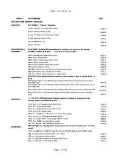
Transcription of CERTIFIED LIGHTING PACKAGE GUIDE FOR …
1 CERTIFIED LIGHTING PACKAGE GUIDE FOR emergency RESPONSE VEHICLESNFPA phone 1-314-426-27001 TABLE OF CONTENTSL arge Apparatus - Zone Definitions ..2 Small Aparatus - Zone Definitions ..3 Electrical & Warning Standards ..4 Lightbars - Upper Zone A - Front Pursuit ..5 Defender ..6 Triumph ..8 21TR ..9 RX 2700 ..10 RMX ..11 Large Apparatus LIGHTING Upper Zone C - Rear ..12 Upper Zones B & D - Side ..13 Lower Zone A - Front ..14 Lower Zones C - Rear, B & D - Side ..16 Rescue Vehicle Applications Zone A - Front ..18 Zone C - Rear ..19 Zones B & D - Side ..20 Special Applications ..21 NFPA Vehicle Compliant Packages ..22-24 NEW Products ..25 Required Options for Federal Motor Vehicle Safety Standards (FMVSS).
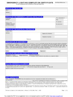
2 26 Accessories ..26 White LIGHTING ..27 Sirens & Speakers ..27 Certificate of Compliance ..28-32 Visit the Code 3 Website ( ) for additional NFPA Tools, Lightbar Configurator (C3 Vue), Product Details and Warranty 1901, 1906, 1917A large apparatus is defined in NFPA 1901 as an apparatus with a bumper-to-bumper length of 25 ft. or more. The upper-level optical warning devices shall be mounted as high and near the corner points of the apparatus as is practi-cal. The lower-level devices shall be between 18 inches and 62 inches above level ground. A mid-ship optical warning device shall be used if the distance between the front and rear lower-level optical devices exceeds 25 feet.
3 The minimum optical warning system should require no more than an average of 40 amps when operating in the blocking mode. Should the apparatus require mid-ship lights, no more than 5 amps of additional current should be required for operation of each set of mid-ship lights. See the NFPA 1901 standards GUIDE for more information and load management demand questions. Amps for Code 3 products are listed in this GUIDE to calculate this demand. There is also an NFPA Compliance Configurator on the C3 Vue found on the Code 3 website s home page ( ).Flash Rate and Failure 75 flashes per minute is the minimum flash rate allowed for a single optical source. 150 flashes per minute from all of the light sources visible at any data point ( two warning lights are required per zone).
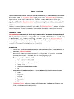
4 Failure of a LIGHTING product should not leave a zone area without a LIGHTING source. Mid-Ship Lights Additional mid-ship lights must be added to lower B & D Zones on a Large Apparatus so that you always maintain a horizontal distance of 25 feet or less between all centers of the lower level warning lights. See minimum mid-ship LIGHTING example for Zone B & D below:Large Apparatus - Standard for Electrical Systems and Warning Devices ZONE AFrontZONE C RearZONE BSideZONE DSide Calling for BlockingColor Right of Way Right of WayRed Any Zone Any ZoneBlue Any Zone Any ZoneAmber Any Zone Except A (front) Any ZoneWhite Any Zone Except C (rear) Not PermittedZONE A1000K (Calling)400K (Blocking)ZONE C400K (Calling)800K (Blocking)ZONE B400K (Both)ZONE D400K (Both)Permissible ColorsThe table below lists SAE J578 color specifications:Light Energy Requirements for Large ApparatusValues in Candela-Seconds per MinuteUpper Level.
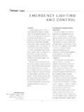
5 ZONE A150K (Both)ZONE C150K (Both)ZONE B150K (Both)ZONE D150K (Both)Lower Level:For vehicles 25 feet or longer the light output at each data point on the horizontal plane must be a minimum of 10K and at + 5 Modes Calling for Right of Way (Responding) - Apparatus responding to an emergency . Blocking Right of Way - Blocking right of way (At Scene). White light not permitted. 25 25 Mid-Ship Lights (shown in red) phone 1-314-426-27003 NFPA 1901, 1906, 1917A small apparatus is defined in NFPA 1901 as an apparatus whose bumper-to-bumper length is less than 25 feet. The upper-level warning devices should be mounted high, but not over 8 feet, at the optical center.
6 One or more lower-level warning devices shall be mounted close to the front corner(s) of the apparatus with the distance between 18 inches and 48 inches from the ground. Each apparatus is divided into eight (8) warning zones. Zones A - D are illustrated above and they can be divided into upper and lower sections. For Small Apparatus the optical zone requirements are a total of the Upper and Lower minimum optical warning system should require no more than an average of 35 amps when operating in the blocking mode. See the NFPA 1901 standards GUIDE for more information and load management demand questions. Amps for Code 3 products are listed in this GUIDE to calculate this demand.
7 There is also an NFPA Compliance Configurator on the C3 Vue found on the Code 3 website s home page ( ).Flash Rate and Failure 75 flashes per minute is the minimum flash rate allowed for a single optical source. 150 flashes per minute from all of the light sources visible at any data point (ex. two warning lights are required per zone). Failure of a LIGHTING product should not leave a zone area without a LIGHTING source. Small Apparatus - Standard for Electrical Systems and Warning DevicesZONE AFrontZONE CRearZONE BSideZONE DSide Calling for BlockingColor Right of Way Right of WayRed Any Zone Any ZoneBlue Any Zone Any ZoneAmber Any Zone Except A (front) Any ZoneWhite Any Zone Except C (rear) Not PermittedZONE A1000K (Calling)400K (Blocking)ZONE C400K (Calling)800K (Blocking)ZONE B200K (Both)ZONE D200K (Both)Permissible ColorsThe table below list SAE J578 color specifications:Light Energy Requirements for Small ApparatusValues in Candela-Seconds per MinuteThe above chart combines upper and lower Modes Calling for Right of Way (Responding) - Apparatus responding to an emergency .
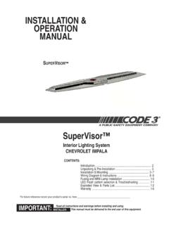
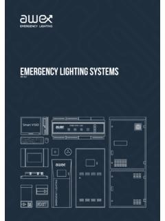
8 Blocking Right of Way - Blocking right of way (At Scene). White light not 90 Each Zone on a Large or Small Apparatus consists of 19 data points (10,000 ) where light energy is Upper Zones Shared LightingStandard for Electrical Systems and Warning DevicesZONE AFrontZONE CRearZONE BSideZONE DSideExplanation of FlagnotesZone AFront2A12D4D5D4B3B3A5 BZone DDriver SideZone BPassenger SideZone CRearWarningDeviceWarningDevice1. Use of LEDs in the Standard location for Zone & 3. Use of one corner LED for its contribution to Zone A. Note: These corner LEDs also contribute light to the adjacent sides Zones B and Use of lightbar LEDs for its contribution to side Zones B and D.
9 5. (Optional) use of a rear-facing corner LED for its contribution to side Zones B and and Light Sharing1. Components explicitly selected for Zone B are assumed to also be specified for Zone D. 2. Often a device, such as a rotator, can be positioned at the rear corner so that its light contributes to Zone C and the adjacent side zones; B and D. Be sure to use the Supplemental Light Sources worksheet to add the contribution of such a single device to both Sometimes the shared light is not the same for the two adjacent side zones. For example, the rear of a vehicle might have a Red and an Amber device as shown. Light output can vary from device to device based on color emitting from the device.
10 Use the lower of the two for the contribution calculation for the side zones, , use the values for the lesser output device for the Zone B and D qualification rather than the higher configurations are shown on the following lightbar pages. Additional options may be added to these lightbars. The additional lightbar options will add to the light output of the lightbar. Any additional light options can be load managed per NFPA GUIDE is a compilation of NFPA CERTIFIED LIGHTING devices prepared by Code 3 , Inc. When this GUIDE is used along with the Certificate of Compliance worksheet, pages 28-32 of this GUIDE , you will be able to design a completely NFPA- CERTIFIED optical warning device system.