Transcription of INSTALLATION & OPERATION MANUAL
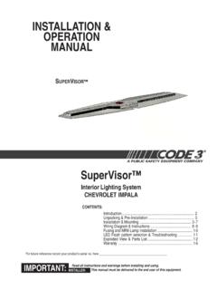
1 INSTALLATION . & OPERATION . MANUAL . SUPERVISOR . SuperVisor . Interior Lighting System CHEVROLET TAHOE and other identical interior cab GM vehicles CONTENTS: Unpacking & INSTALLATION & Wiring Diagram & Fusing and MR8 Lamp LED Flash pattern selection ..11. Exploded View & Parts For future reference record your product's serial no. here _____. Read all instructions and warnings before installing and using. IMPORTANT: INSTALLER: This MANUAL must be delivered to the end user of this equipment. Introduction The SuperVisor is an interior lighting system that fits in the visor area near the top of the windshield. It delivers an amazing warning signal, including MR8 powered takedown lights.
2 The SuperVisor is designed on a modular basis, which means that the light bar can be customized to meet most any requirement. The SuperVisor has room for up to eight LED lightheads plus two MR8 takedowns. Each lighthead is individually wired for any flash pattern or combination of flash patterns required. The use of this or any warning device does not ensure that all drivers can or will observe or react to an emergency warning signal. Never take the right-of-way for granted. It is your responsibility to be sure you can proceed safely before entering an intersection, driving against traffic, responding at a high rate of speed, or walking on or around traffic lanes.
3 The effectiveness of this warning device is highly dependent upon correct mounting and wiring. Read and follow the manufacturer's instructions before installing or using this device. The vehicle operator should insure daily that all features of the device operate correctly. In use, the vehicle operator should insure the projection of the warning signal is not blocked by vehicle components ( : open trunks or compartment doors), people, vehicles, or other obstructions. This equipment is intended for use by authorized personnel only. It is the user's responsibility to understand and obey all laws regarding emergency warning devices.
4 The user should check all applicable city, state and ! federal laws and regulations. Code 3, Inc., assumes no liability for any loss resulting from the use of this warning device. WARNING! Proper INSTALLATION is vital to the performance of this warning device and the safe OPERATION of the emergency vehicle. It is important to recognize that the operator of the emergency vehicle is under psychological and physiological stress caused by the emergency situation. The warning device should be installed in such a manner as to: A) Not reduce the output performance of the system, B) Place the controls within convenient reach of the operator so that he can operate the system without losing eye contact with the roadway.
5 Emergency warning devices often require high electrical voltages and/or currents. Properly protect and use caution around live electrical connections. Grounding or shorting of electrical connections can cause high current arcing, which can cause personal injury and/or severe vehicle damage, including fire. Any electronic device may create or be affected by electronmagnetic interference. After INSTALLATION of any electronic device operate all equipment simultaneously to insure that OPERATION is free of interference. Never power emergency warning equipment from the same circuit or share the same grounding circuit with radio communication equipment.
6 PROPER INSTALLATION COMBINED WITH OPERATOR TRAINING IN THE PROPER USE OF EMER- GENCY WARNING DEVICES IS ESSENTIAL TO INSURE THE SAFETY OF EMERGENCY PERSONNEL. AND THE PUBLIC. All devices should be mounted in accordance with the manufacturer's instructions and securely fastened to vehicle elements of sufficient strength to withstand the forces applied to the device. Driver and/or passenger airbags (SRS) will affect the way equipment should be mounted. This device should be mounted by permanent INSTALLATION and within the zones specified by the vehicle manufacturer, if any. Any device mounted in the deployment area of an air bag will damage or reduce the effectiveness of the air bag and may damage or dislodge the device.
7 Installer must be sure that this device, its mounting hardware and electircal supply wiring does not interfere with the air bag or the SRS wiring or sensors. Mounting the unit inside the vehicle by a method other than permanent INSTALLATION is not recommended as unit may become dislodged during swerving, sudden braking or collision. Failure to follow instructions can result in personal injury. 2. Unpacking & Pre- INSTALLATION Carefully remove the SuperVisor and place it on a flat surface, taking care not to scratch the lenses or damage the cable coming out of the side. Examine the unit for transit damage, broken lamps, etc.
8 Report any damage to the carrier and keep the shipping carton. Standard light bars are built to operate on 12 volt negative ground (earth) vehicles. If you have an electrical system other than 12. volt negative ground (earth), and have not ordered a specially wired light bar, contact the factory for instructions. Test the unit before INSTALLATION . To test, touch the black, (and if present grey, purple, and brown) wire(s) to the ground (earth) and the other wires to +12 volts , in accordance with the instructions attached to the cable (an automotive battery is preferable for this test). A. battery charger may be used, but please note that some electronic options (flashers, stingrays, etc.)
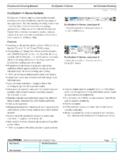
9 May not operate normally when powered by a battery charger. If problems occur at this point, contact the factory. INSTALLATION & Mounting Utilizing non-factory supplied screws and/or mounting brackets and/or the improper number WARNING! ! of screws may result in loss of warranty coverage on the equipment. Mounting Hardware - All mounting hardware is packed in a small box inside the main carton. There are four brackets used to mount the visor bar to the vehicle. These are discussed in detail later. Removing Sun Visors Begin the INSTALLATION by removing the Chevrolet Tahoe's driver and passenger sun visors. There are three screws that hold the pivotal arm of the sun visor to the headliner.
10 Remove the two outer screws using a small torx screwdriver. Note: Reverse thread the screws until they just release the visor pivot arm from the headliner, this keeps the screws attached to the visor pivot arm bracket so that they are not easily lost. Unclip the sun visor and rotate it over to expose the last screw (as shown in Figure 1). It is not necessary to unplug the visor vanity light wires (see figure 2). If the visor vanity light wires are unplugged identify each visor with tape or other marking to indicate the driver from the passenger side unit (they are not identical). FIGURE 1 FIGURE 2. 3. Attach brackets to sun visor retaining clips In order to remove the sun visor retaining clip, unscrew the single torx screw holding it in place (see figure 3).