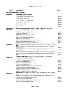
Transcription of SIRENS AND CONTROLS - Code 3, Inc.
1 1 INSTALLATION& OPERATIONMANUAL3890 SERIESMASTERCOM 2 Standard 2 Unpacking & 4 Installation & 5 Set-Up and 11 Maintenance .. 14 Parts List (Replacement Parts / Exploded View)16 Wiring 20 External Ignition Lead Relay .. 21 Common MIC 23 Notes .. 25 Warranty .. 26 SIRENS AND CONTROLSRead all instructions and warnings before installing and This manual must be delivered to the end user of this :2 IntroductionThe enhanced 3890 series siren is an improved series of electronic SIRENS that has been designed to meetthe needs of all emergency vehicles. This series of SIRENS incorporates the popular packaging and featuresof the original Mastercom siren with microprocessor based circuitry and MOSFET technology. Most of theoriginal Mastercom features are available along with many new added features that are not available on anyother Code 3 siren such as; Park Kill, Instant "ON", Adj.
2 Backlighting, " Scroll " Mode and FeaturesThe enhanced 3890 series SIRENS consist of integrated CONTROLS and amplifier in a single package with 4 and6 circuit lighting CONTROLS available as well. The models are as follows:3892- Primary Tones: Wail, Yelp, Hi-Lo, Air Horn- Secondary Tones: HyperYelp, HyperLo3892L4,L6- Primary Tones: Wail, Yelp, Hi-Lo, Air Horn- Secondary Tones: HyperYelp, HyperLo- 4 or 6 auxillary lighting controls2 SIRENS are an integral part of an effective audio/visual emergency warning , SIRENS are only short range secondary warning devices. The use of a sirendoes not insure that all drivers can or will observe or react to an emergency warningsignal, particularly at long distances or when either vehicle is traveling at a high rate ofspeed. SIRENS should only be used in a combination with effective warning lights andnever relied upon as a sole warning signal.
3 Never take the right of way for granted. It isyour responsibility to be sure you can proceed safely before entering an intersection,driving against traffic, or responding at a high rate of effectiveness of this warning device is highly dependent upon correct mounting andwiring. Read and follow the manufacturer s instructions before installing or using thisdevice. The vehicle operator should check the equipment daily to insure that all featuresof the device operate be effective, SIRENS must produce high sound levels that potentially can inflict hearingdamage. Installers should be warned to wear hearing protection, clear bystanders fromthe area and not to operate the siren indoors during testing. Vehicle operators andoccupants should assess their exposure to siren noise and determine what steps, suchas consultation with professionals or use of hearing protection should be implemented toprotect their equipment is intended for use by authorized personnel only.
4 It is the user s respon-sibility to understand and obey all laws regarding emergency warning devices. The usershould check all applicable city, state and federal laws and 3, Inc., assumes no liability for any loss resulting from the use of this installation is vital to the performance of the siren and the safe operation of theemergency vehicle. It is important to recognize that the operator of the emergencyvehicle is under psychological and physiological stress caused by the emergency situa-tion. The siren system should be installed in such a manner as to: A) Not reduce theacoustical performance of the system, B) Limit as much as practical the noise level in thepassenger compartment of the vehicle, C) Place the CONTROLS within convenient reach ofthe operator so that he can operate the system without losing eye contact with the warning devices often require high electrical voltages and/or currents.
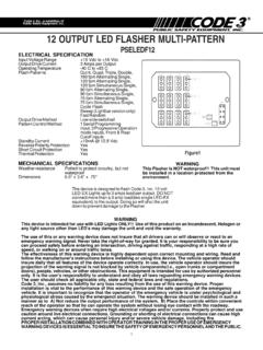
5 Prop-erly protect and use caution around live electrical connections. Grounding or shorting ofelectrical connections can cause high current arcing, which can cause personal injuryand/or severe vehicle damage, including INSTALLATION COMBINED WITH OPERATOR TRAINING IN THE PROPERUSE OF EMERGENCY WARNING DEVICES IS ESSENTIAL TO INSURE THE SAFETYOF EMERGENCY PERSONNEL AND THE !!3 GUNEMGSGN LTDRTDAYOUR POLICE DEPT.'S NAME HERE (OPTION)VOLUMEYELPRADIOHI-LOSTANDBYWAILA IR HORNMANUALLI GHTINGMODEL 3894L6PA/RRBV olumeControlSwitchRotarySelectorSwitchSw itch ASwitch BSwitch CSwitch DSwitch ESwitch FFigure 1 - control PanelHorn RingSelectSlide Switch3894L6S same features as 3892L6 with anaddation of a rear panel connector toaccommodatea single microphone following features are standard in the newstyle 3890 series (tones and sequences maydiffer by model number):Instant-On- There is no " ON/OFF " switch. Selecting anysiren function, or keying the microphone will activate thesiren assuming the siren is connected directly to a non-ignition switched source of + TM (L4 and L6 Models Only)- An interlock circuitbetween the siren and the light control circuits that permitsautomatic siren tones only when the progressive switch is in Level 3 or in Level 2 or 3 (user selectable - worksin conjunction with the horn transfer relay).
6 This feature is used in jurisdictions that require warning lights to beon before the siren is Kill- This feature deactivates the siren tones when the vehicle is shifted into park. Once PKILL isactivated the siren will remain deactivated until an action occurs such as moving the selector switch toSTANDBY, returning lighting level switch to position one or keying the microphone. Any action will enable thesiren tones to function again with the exception of the auxillary lighting lighting models this alsodrops-out the Level 3 lighting output for a power- down mode when in Backlighting- Backlighting is independent of siren power. Allows connecting to dimmer if Power- Allows user to power the two-way radio from the siren when the ignition is "OFF".Automatic Short Circuit Protection- The siren will sense a short circuit on the speaker terminals andautomatically go to standby until the fault is removed. Once the fault is removed the siren will return to Level "3 " Drop-out- When vehicle is shifted to PARK and the PKILL feature is connected, Level 3lighting will drop-out.
7 This is indicated by the "red" LED exstinguishing. This is a power down mode and can bedefeated by setting the 4 -position rear dip switch to the PKILL "OFF" position on the lighting Mode- Setting the slide switch on the rear of the siren to the SCROLL position will put siren in scrollmode. This will allow "scrolling" through tones utilizing sharp taps on the horn ring, or a switch, via the Remotesiren input. In this mode holding the horn ring for prolonged durations will produce the Airhorn sound. SeeOPERATION section for further Mode - Setting the slide switch on the rear of the siren to the Hit-N-Go position will put the siren in theHit-n-Go mode will be most familiar to existing Mastercom users. A seven second override isstandard for all tones when activated by the Manual button or the Remote OPERATION section Siren Tones - Industry standard Wail, Yelp, and Hi-Lo HORN Tone - Electronic AIR HORN Public Address - Public Address override of all siren functions when the microphone Push-to-Talk keyis LED - An indicator LED, visible on the front panel that informs the operator of the status of his siren atall Rebroadcast - Broadcast Two-way radio reception over siren speakers.
8 These inputs are transformercoupled to prevent loading of the PAVolumeAdjust4 Remote Siren Switching - The siren accepts either a positive or a ground (earth) signal, usually from thevehicle's horn switch (or other user supplied switch), and remotely activates the MANUAL or AIR HORN (ifsupplied) function. Selection is made via the front panel slide siren is factory set for a GND(Earth) signal and may be reconfigured to accept a positive signal. See Set-up and Adjustments sectionfor Priority/Manual Wail - The following tones are produced while pushing the MANUAL Push-button ortriggering the user-supplied REMOTE siren switch:Manual Wail when the MANUAL Push-button is depressed while the rotary switch is in the STANDBY when the MANUAL Push-button is depressed while the rotary switch is in the WAIL when the MANUAL Push-button is depressed and the rotary switch is in the YELP when the MANUAL Push-button is depressed and the rotary switch is in the HI-LO Cancelling Microphone - Wired in microphone that is easily unplugged internally for service Distribution Section - A three level progressiveswitch for primary warning light system control plus 4 push-on/push-off auxiliary switches that are user convertible tomomentary action ('L4 models).
9 The unit may also bepurchased with 6 auxiliary switches ('L6 models).Each auxiliary switch can be custom labeled with thesupplied label kit. Each label is backlit and increasesintensity when activated to alert the operator. Each positionof the progressive switch has its own indicator Ring Transfer - ('L models only) Built in horn transferrelay that may be activated at Levels 2 and 3 of the warninglight progressive switch. Point of activation is customerselectable with the rear panel DIP & Pre-installationAfter unpacking your 3890 series siren, carefully inspect the unit and associated parts for any damage that mayhave been caused in transit. Report any damage to the carrier immediatelyAll devices should be mounted in accordance with the manufacturer s instructions andsecurely fastened to vehicle elements of sufficient strength to withstand the forces appliedto the device. Ease of operation and convenience to the operator should be the primeconsideration when mounting the siren and CONTROLS .
10 Adjust the mounting angle to allowmaximum operator visibility. Do not mount the control Head Module in a location that willobstruct the drivers view. Mount the microphone clip in a convenient location to allow theoperator easy access. Devices should be mounted only in locations that conform to theirSAE identification code as described in SAE Standard J1849. For example, electronicsdesigned for interior mounting should not be placed underhood, should be placed within convenient reach of the driver or if intended for twoperson operation, the driver and/or passenger. In some vehicles, multiple control switchesand/or using methods such as "horn ring transfer" which utilizes the vehicle horn switch totoggle between siren tones may be necessary for convenient operation from two should be placed within convenient reach* of the driver or if intended for twoperson operation the driver and/or passenger. In some vehicles, multiple control switchesand/or using methods such as horn ring transfer which utilizes the vehicle horn switch totoggle between siren tones may be necessary for convenient operation from two 2 WARNING!