Transcription of Chapter 17 Heat Exchangers - link.springer.com
1 Chapter 17 heat ExchangersA number of technologies are being investigated for the Next Generation NuclearPlant that will produce heated fluids at significantly higher temperatures thancurrent generation power plants. The higher temperatures offer the opportunity tosignificantly improve the thermodynamic efficiency of the energy conversion of the concepts currently under study is the Molten Salt Reactor. The coolantfrom the Molten Salt Reactor may be available at temperatures as high as800 1000 C. At these temperatures, an open Brayton cycle combined with aRankine bottoming cycle appears to have some strong advantages. Thermodynamicefficiencies approaching 50% appear possible. Requirements for circulating coolingwater will be significantly reduced. However, to realistically estimate the efficien-cies achievable it is essential to have good models for the heat Exchangers involvedas well as the appropriate turbo-machinery.
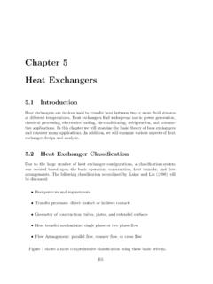
2 This study has concentrated on model-ing all power conversion equipment from the fluid exiting the reactor to the energyreleases to the heat exchanger TypesA heat exchanger is a heat transfer device that exchanges heat between two or moreprocess fluids. heat Exchangers have widespread industrial and domestic applica-tions. Many types of heat Exchangers have been developed for use in steam powerplants, chemical processing plants, building heat and air conditioning systems,transportation power systems, and refrigeration actual design of heat Exchangers is a complicated problem. It involves morethan heat transfer analysis alone. Cost of fabrication and installation, weight, andsize play important roles in the selection of the final design from a total cost ofownership point of view.
3 In many cases, although cost is an important consider-ation, size and footprint often tend to be the dominant factors in choosing a design. Springer International Publishing AG 2017B. Zohuri,Thermal-Hydraulic Analysis of Nuclear Reactors,DOI heat Exchangers may be classified as one of several basic types. The fourmost common types, based on flow path configuration, are illustrated in [1].1. Inconcurrent,orparallel flow, units the two fluid streams enter together at oneend, flow through in the same direction, and leave together at the other Incountercurrent,orcounterflow,units the two streams move in Insingle-pass crossflowunits, one fluid moves through the heat transfer matrixat right angles to the flow path of other Inmultipass crossflowunits, one fluid stream shuttles back and forth across theflow path of the other fluid stream, usually giving a crossflow approximation fluid inCold fluid in(a) Parallel flowCold fluid outHot fluid outHot fluid inHot fluid inHot fluid inCold fluid outCold fluid inCold fluid inCold fluid in(b) Counterflow(c) Single-pass crossflow(d)
4 Multipass crossflowCold fluid outCold fluid outHot fluid outHot fluid outHot fluid outFig. of flowpath configuration throughheat exchanger55417 heat ExchangersThe most important difference between these four basic types lies in the relativeamounts of heat transfer surface areas required to transfer the desired amount ofheat between the two below shows the relative area required for each type as a function ofthe change in temperature of the fluid with the largest temperature change require-ment for a typical set of conditions. In the region in which the fluid temperaturechange across the heat exchanger is a small percentage of the difference intemperature between the two entering fluid streams, all the units require roughlythe same area. The parallel-flow heat exchanger is of interest primarily for appli-cations in this region.
5 Crossflow units have a somewhat broader range of applica-tion and are peculiarly suited to some types of heat exchanger construction thathave special advantages. The counterflow heat exchanger requires the least , it is the only type that can be employed in the region in which thetemperature change in one or both of the fluid streams closely approaches thetemperature difference between the entering fluids addition, heat Exchangers may be classified as direct contact or indirectcontact. In the direct-contact type, heat transfer takes place between two immisciblefluids, such as a gas and a liquid, coming into direct contact. For example, coolingtowers, jet condensers for water vapor, and other vapors utilizing water spray aretypical examples of direct-contact heat transfer surface temperature rise in per cent of inlet temperature difference5060708090 Parallel flowCrossflowCounterflowFig.
6 Required relative heat transfer surface area as a function of the ratio of thetemperature rise (or drop) in the fluid stream having the greater change in temperature to thedifference in temperature between the inlet heat exchanger Types555 AnImmiscible Fluidsare incapable of is being mixed or blended liquids that are shaken together eventually separate into layers. Oiland water are typical immiscible the indirect-contact type of heat Exchangers , such as automobile radiators, thehot and cold fluids are separated by an impervious surface, and they are referred toassurface heat Exchangers . There is no mixing of the two Classification of heat Exchangerby Construction TypeHeat Exchangers also can be classified according to their construction features. Forexample, there are tubular, plate, plate-fin, tube-fin, and regenerative important performance factor for all heat Exchangers is the amount of heattransfer surface area within the volume of the heat exchanger .
7 This is called itscompactness factorand is measured in square meters per cubic Tubular heat ExchangersTubular Exchangers are widely used, and they are manufactured in many sizes, flowarrangements, and types. They can accommodate a wide range of operating pres-sures and temperatures. The ease of manufacturing and their relatively low costhave been the principal reason for their widespread use in engineering commonly used design, called theshell-and-tubeexchanger, consists of roundtubes mounted on a cylindrical shell with their axes parallel to that of the the main features of a shell-and-tube exchanger havingone fluid flowing inside the tubes and the other flowing outside the tubes. TheTubeoutletTubeinletShellinletShellout letBafflesFig. shell-and-tube heat exchanger ; one shell pass and one tube pass [2]55617 heat Exchangersprinciple components of this type of heat exchanger are the tube bundle, shell,front-and-rear end headers, and baffles.
8 The baffles are used to support the tubes, todirect the fluid flow approximately normal to the tubes, and to increase the turbu-lence of the shell fluid. There are various types of baffles, and the choice of baffletype, spacing, and geometry depends on the flow rate allowable shell-side pressuredrop, tube support requirement, and the flow-induced vibrations. Many variationsof shell-and-tube exchanger are available; the differences lie in the arrangement offlow configurations and in the details of heat Exchangers with one shell pass and two tubes passes and with twoshell passes and four tube passes are shown in , b, respectively [3].The character of the fluids may beliquid-to-liquid,liquid-to-gas, Exchangers have the most common applications. Both fluids arepumped through the Exchangers ; hence, the heat transfer on both the tube side andthe shell side is by forced convection.
9 Since the heat transfer coefficient is high withthe liquid flow, generally there is no need to use fins [2].The liquid-to-gas arrangement is also commonly used; in such cases, the finsusually are added on the gas side of the tubes, where the heat transfer coefficientis inletShell inletShell outletabShell outletTube outletTube outletTube inletTube inletFig. heat Exchangers . (a) One shell pass and two tube passes. (b) Two shellpasses and four tube passes [3] Tubular heat Exchangers557 Gas-to-gas Exchangers are used in the exhaust gas and air preheatingrecuperators for gas turbine systems, cryogenic gas-liquefaction systems, andsteel furnaces. Internal and external fins generally are used in the tubes to enhanceheat Plate heat ExchangersAs the name implies, plate heat Exchangers usually are constructed of thin plates may be smooth or may have some form of corrugation.
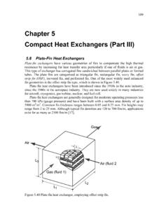
10 Since the plategeometry cannot accommodate as high-pressure and/or temperature differentials asa circular tube, it is generally designated for moderate temperature and/or pressuredifferentials of the compactness factor, which for plate Exchangers ranges fromabout 120 to 230 m2 Plate-Fin heat ExchangersThe compactness factor can be significantly improved ( , up to about 6000 m2/m3)by using the plate-fin type of heat exchanger . illustrates typical plate-finconfigurations. Flat plates separate louvered or corrugated fins. Crossflow, counter-flow, or parallel-flow arrangements can be obtained readily by properly arranging thefins on each side of the plate. Plate-fin Exchangers are generally used for gas-to-gasapplications, but they are used for low-pressure applications not exceeding about10 atm ( , 1000 kPa).