Transcription of CHAPTER 3 Boolean Algebra and Digital Logic
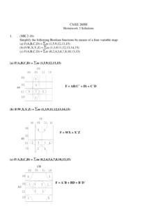
1 CMPS375 Class Notes (Chap03) Page 1 / 28 Dr. Kuo-pao Yang CHAPTER 3 Boolean Algebra and Digital Logic Introduction 137 Boolean Algebra 138 Boolean Expressions 139 Boolean Identities 140 Simplification of Boolean Expressions 142 Complements 144 Representing Boolean Functions 145 Logic Gates 147 Symbols for Logic Gates 147 Universal Gates 148 Multiple Input Gates 149 Digital Components 150 Digital Circuits and Their Relationship to Boolean Algebra 150 Integrated Circuits 151 Putting It All Together: From Problem Description to Circuit 153 Combinational Circuits 155 Basic Concepts 155 Examples of Typical Combinational Circuits 155 Sequential Circuits 162 Basic Concepts 163 Clocks 163 Flip-Flops 163 Finite State Machines 167 Examples of Sequential Circuits 173 An Application of Sequential Logic : Convolutional Coding and Viterbi Detection 178 Designing Circuits 184 CHAPTER Summary 185 Focus on Karnaugh Maps 199 Introduction 199 Description of Kmaps and Terminology 199 Kmap Simplification for Two Variables 201 Kmap Simplification for Three Variables 202 Kmap Simplification for Four Variables 205 Don t Care Conditions 208 Summary 209 CMPS375 Class Notes (Chap03) Page 2 / 28 Dr.
2 Kuo-pao Yang Introduction 137 In 1854 George Boole introduced a systematic treatment of Logic and developed for this purpose an algebraic system known as symbolic Logic , or Boolean Algebra . Boolean Algebra is a branch of mathematics and it can be used to describe the manipulation and processing of binary information. The two-valued Boolean Algebra has important application in the design of modern computing systems. This CHAPTER contains a brief introduction the basics of Logic design. It provides minimal coverage of Boolean Algebra and this Algebra s relationship to Logic gates and basic Digital circuit. Boolean Algebra 138 Boolean Algebra is Algebra for the manipulation of objects that can take on only two values, typically true and false. It is common to interpret the Digital value 0 as false and the Digital value 1 as true. Boolean Expressions 139 Boolean Expression: Combining the variables and operation yields Boolean expressions.
3 Boolean Function: A Boolean function typically has one or more input values and yields a result, based on these input value, in the range {0, 1}. A Boolean operator can be completely described using a table that list inputs, all possible values for these inputs, and the resulting values of the operation. A truth table shows the relationship, in tabular form, between the input values and the result of a specific Boolean operator or function on the input variables. The AND operator is also known as a Boolean product. The Boolean expression xy is equivalent to the expression x * y and is read x and y. The behavior of this operator is characterized by the truth table shown in Table TABLE The Truth Table for AND CMPS375 Class Notes (Chap03) Page 3 / 28 Dr. Kuo-pao Yang The OR operator is often referred to as a Boolean sum. The expression x+y is read x or y.
4 The truth table for OR is shown in Table TABLE The Truth Table OR Both xand x are read as NOT x. The truth table for NOT is shown in Table TABLE The Truth Table for NOT The rule of precedence for Boolean operators give NOT top priority, followed by AND, and then OR TABLE The Truth Table for F(x, y, z) = x + y z CMPS375 Class Notes (Chap03) Page 4 / 28 Dr. Kuo-pao Yang Boolean Identities 140 Boolean expression can be simplified, but we need new identities, or laws, that apply to Boolean Algebra instead of regular Algebra . TABLE Basic Identities of Boolean Algebra DeMorgan s law provides an easy way of finding the complement of a Boolean function. TABLE Truth Tables for the AND Form of DeMorgan s Law CMPS375 Class Notes (Chap03) Page 5 / 28 Dr. Kuo-pao Yang Simplification of Boolean Expressions 142 The algebraic identities we studied in Algebra class allow us to reduce algebraic expression to their simplest form.
5 EXAMPLE EXAMPLE How did we know to insert additional terms to simplify the function? Unfortunately, there no defined set of rules for using these identities to minimize a Boolean expression: it is simply something tat comes with experience. To prove the equality of two Boolean expressions, you can also create the truth tables for each and compare. If the truth tables are identical, the expressions are equal. Example using Identities Complements 144 F(x, y, z) = x + yz and its complement, F (x, y, z) = x(y + z) TABLE Truth Table Representation for a Function and Its Complement CMPS375 Class Notes (Chap03) Page 6 / 28 Dr. Kuo-pao Yang Representing Boolean Functions 145 In fact, there are an infinite number of Boolean expressions that are logically equivalent to one another. Two expressions that can be represented by the same truth table are considered logically equivalent.
6 EXAMPLE The two most common standardized forms are the sum-of-products form and the product-of-sums form. In the sum-of-products form, ANDed variables are ORed together. For example, In the product-of-sums form, ORed variables are ANDed together. For example, The sum-of-products form is usually easier to work with and to simplify, so we use this form exclusively in the sections that follow. It is easy to convert a function to sum-of-products form using its truth table. We are interested in the values of the variables that make the function true (=1). Using the truth table, we list the values of the variables that result in a true function value. Each group of variables is then ORed together. EXAMPLE TABLE Truth Table Representation for the Majority Function sum-of-products: F(x, y, z) = x yz + xy z + xyz + xyz CMPS375 Class Notes (Chap03) Page 7 / 28 Dr.
7 Kuo-pao Yang Logic Gates 147 We see that Boolean functions are implemented in Digital computer circuits called gates. A gate is an electronic device that produces a result based on two or more input values. o In reality, gates consist of one to six transistors, but Digital designers think of them as a single unit. o Integrated circuits contain collections of gates suited to a particular purpose. Symbols for Logic Gates 147 The three simplest gates are the AND, OR, and NOT gates. FIGURE The Three Basic Gates Another very useful gate is the exclusive OR (XOR) gate. The output of the XOR operation is true only when the values of the inputs differ. FIGURE The exclusive OR (XOR) Gate CMPS375 Class Notes (Chap03) Page 8 / 28 Dr. Kuo-pao Yang Universal Gates 148 Two other common gates are nand and NOR, which produce complementary output to AND and OR.
8 FIGURE and The Truth Table and Logic Symbols for nand and NOR Gates nand and NOR are known as universal gates because they are inexpensive to manufacture and any Boolean function can be constructed using only nand or only NOR gates. FIGURE Three Circuits Constructed Using Only nand Gates Multiple Input Gates 149 Gates can have multiple inputs and more than one output. FIGURE , , and CMPS375 Class Notes (Chap03) Page 9 / 28 Dr. Kuo-pao Yang Digital Components 150 Every computer is built using collections of gates that are all connected by way of wires acting as signal gateway. Digital Circuits and Their Relationship to Boolean Algebra 150 More complex Boolean expressions can be represented as combinations of AND, OR, and NOT gates, resulting in a Logic diagram that describes the entire expression. FIGURE A Logic Diagram for F(x, y, z) = x + y z Integrated Circuits 151 Gates are not sold individually; they are sold in units called integrated circuits (ICs).
9 A chip (a small silicon semiconductor crystal) is a small electronic device consisting of the necessary electronic components (transistors, resistors, and capacitors) to implement various gates. The first IC were called SSI chips and contained up to 100 electronic components per chip. We now have ULSI (ultra large-scale integration) with more than 1 million electronic components per chip. FIUGRE A simple SSI Integrated Circuit CMPS375 Class Notes (Chap03) Page 10 / 28 Dr. Kuo-pao Yang Example: o The Boolean circuit: F(x, y, z) = x y o Can be rendered using only nand gates as: o So we can wire the pre-packaged circuit to implement our function: F(x, y, z) = x y CMPS375 Class Notes (Chap03) Page 11 / 28 Dr. Kuo-pao Yang Putting It All Together: From Problem Description to Circuit 153 Boolean Logic is used to solve practical problems.
10 Expressed in terms of Boolean Logic practical problems can be expressed by truth tables. Truth tables can be readily rendered into Boolean Logic circuits. Example o Suppose we are to design a Logic circuit to determine the best time to plant a garden. We consider three factors (inputs): (1) Time, where 0 represents day and 1 represents evening; (2) Moon phase, where 0 represents not full and 1 represents full; and (3) Temperature, where 0 represents 45 F and below, and 1 represents over 45 F. We determine that the best time to plant a garden is during the evening with a full moon. o This results in the following truth table: o From the truth table, we derive the circuit: CMPS375 Class Notes (Chap03) Page 12 / 28 Dr. Kuo-pao Yang Combinational Circuits 155 Digital Logic chips are combined to give us useful circuits. These Logic circuits can be categorized as either combinational Logic (Section ) or sequential Logic (Sec.)