Transcription of Closed Loop Control of Non-Isolated Bidirectional Dc/Dc ...
1 IOSR Journal of Engineering (IOSRJEN) e-ISSN: 2250-3021, p-ISSN: 2278-8719 Vol. 3, Issue 6 (June. 2013), ||V3|| PP 37-43 37 | P a g e Closed Loop Control of Non-Isolated Bidirectional Dc/Dc converter Soumya Manoharan, 1 2, 1, PG scholar, Francis Xavier Engg College, Tirunelveli. 2, Associate Professor , Francis Xavier Engg College, Tirunelveli. Abstract: In this project a Bidirectional dc-dc converter using ZVS technique employs a coupled inductor is implemented. In step-up mode, the coupled inductors are parallely charged and serially discharged to get a high output voltage gain. In step-down mode, the coupled inductors are serially charged and parallely discharged to get a low output voltage gain. Current system using ordinary switching techniques, so that the switching loss is very high. Therefore more heat will dissipated. In ZVS technique, heat loss is minimum. So we can increase the life span of switches.
2 Moreover, we can increase the output voltage. The proposed converter aims to reduce the switching current. It has higher step-up and step-down voltage gains than the conventional Bidirectional dc-dc converter . For the same electric conditions, the proposed converter s and the conventional Bidirectional converter s efficiency, voltage gain, output voltage and switching current will Closed loop Control is using a PID controller,we can obtain a high output voltage and high gain by controlling the duty cycle of switches. I. INTRODUCTION A DC to DC converter is an electronic circuit which converts direct current from one voltage level to another. It is a type of power to DC converter are used in portable electronic devices such as cellular phones and laptop computers,which are supplied from batteries primarly. Such electronic devices mostly contain several sub-circuits,that are different from that supplied by the battery or any external supply,may be higher or lower than the supply voltage.
3 Moreover,the battery voltage decreases as its stored power is DC-DC converters offer a method to increase voltage from a partially lowered battery voltage ,thereby save the space instead of using a no:of DC-DC converters will regulate the output. High efficiency LED power sources,belong to the type of DC-Dc converters,which regulates the current through the LEDs,and the charge pumps will double or triple the input voltage. A bi d i r e c t i on a l DC-DCc on v e r t e r is u s e d f or dc-dc c on v e r s i on p r oc e s s .The power converter has two full bridge converters,one act as inverter and other as bi d i r e c t i on a l DC-DC c on v e r t e r is suitable for electrical vehicle applications. It has advantages of simple circuit with soft switching implementation(ZVS),without additional have high efficiency and simple Control . This advantages make the converter applicable for low,medium and high power applications;mainly for auxillary power suppl y in fuel cell vehicles and power generation.
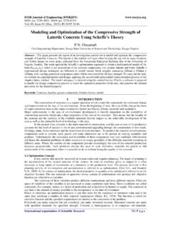
4 It is used in applications where high power density,low cost,low weight and high reliability power converters are required. M i c ro C on t r ol l e r is u s e d to c r e a te p u l s e s f or s wi t c h e s . It t r i g g e r , op e r a t e and c on t r ol M O S F E T S d e vi c e s . PWM technique is used to reduce the harmonics and noises in the circuit. II. CLASSIFICATION Most of the existing bi d i r e c t i on a l DC-DC c on v e r t e r s has the basic circuit structure shown in Figure 1, which is fed by a current or voltage on one side. Based on the auxiliary energy storage and conduction period,the bi d i r e c t i on a l dc-dc c on v e r t e r c a n be c l a s s i fi e d i n t o bu c k a n d b o o s t c on v e r t e r s . T h e bu c k t yp e h a v e e n e r g y s t or a g e p l a c e d on t h e h i g h vol t a g e wi t h l o w c on d u c t i on p e r i o d , a n d t h e bo o s t t yp e h a ve it p l a c e d on t h e l o w v ol t a g e s i d e wi t h h i gh c on d u c t i on p e r i o d.
5 It is classified into two types: isolated Dc/Dc Bi d i r e c t i on a l C on v e r t e r Non- isolated Dc/Dc Bi d i r e c t i on a l C on v e r t e r a. isolated Dc/Dcb i d i r e c t io n a l C o nv e r t e r In the Bi d i r e c t i on a l DC-DC C on ve r t e r s , i s ol a t i o n is d on e by u s i n g a t r a n s f or m e r . T h e t r a n s f or m e r wi l l c a u s e a d d i t i on a l c os t a n d l os s e s . T h e t r a n s f or m e r c a n i s ol a t e t h e v ol t a g e s ou r c e s a n d m a t c h t h e i m p e d a n c e b e t w e e n t h e m . So it is u s e d f or g a l va n i c Closed Loop Control of Non-Isolated Bidirectional Dc/Dc converter 38 | P a g e i s ol a t i on p u r p o s e s . I n d u ct a n c e is p r o v i d e d b e t w e e n t w o c u r r e n t s o u r c e s . F u l l br i d g e , h a l f br i d g e or p u s h-p u l l c i r c u i t s a r e u s e d f or isolated bi d i r e c t i on a l dc-dc c on v e r t e r.
6 Galvanic isolation between inverter and converter circuits,high output voltage gain,high power applications and additional safety are its advantages. b. Non- isolated Dc/Dc B i d i r e c t io na l C o nv e r t e r In Non- isolated Bi d i r e c t i on a l DC-DC C on v e r t e r there is no transformer. isolated Bi d i r e c t i on a l DC-DC C on v e r t e r is u s e d f or g a l va n i c i s ol a t i on p u r p os e s . T h i s wi l l a d d a d di t i on a l s i z e , w e i g h t a n d c o s t . So t r a n s f or m e r-l e s s t yp e is p r e f f e r e d . Non- isolated Bi d i r e c t i on a l DC-DC C on ve r t e r is u s e d in h i g h p o w e r , s p a c e c r a ft a p p l i c a t i on s a n d in a p p l i c a t i on s wh e r e l o w w e i g h t a n d s i z e is r e q u i r e d . It is a c om b i n a t i on of s t e p-up a n d step-d o wn s t a g e s . It h a s a n t i p a r a l l e l l y c on n e c t e d r e c t i fi e r a n d i n ve r t e r c i r c u i t s.
7 In m ot or d r i ve op e r a t i on s , t h e s t e p-up s t a g e is u s e d i n c r e a s e ba t t e r y v o l t a g e . S t e p-d o wn s t a g e is u s e d to br e a k c u r r e n t in ve h i c l e r e g e n e r a t i v e br e a k i n g . Inorder to reduce the disadvantages of isolated Bi d i r e c t i o n a l DC-DC C on v e r t e r , h e r e we a r e u s i n g a N on- isolated Bi d i r e c t i on a l DC-DC C on ve r t e r . III. MODE ZVS technique is used to Control the switches. Here S1 and S2 are the main switches and S3 is the auxillary switch. Conventional Bidirectional dc-dc converter . The inductance of the coupled inductors are same,because ther primary and secondary windings are same. The mutual inductance is given by, where k is the coupling coefficient of the coupled inductor. The voltages across L1 and L2 is: The Bidirectional converter has two modes of operations: continuous mode (CCM) and discontinuous mode(DCM).
8 A) CCM Operation 1) Firstly S1 and S2 are conducting and S3 is in OFF position. The supply from the low voltage side is passed to the coupled inductors. They get parallelly get charged towards the ,the voltage across the two inductors are same and they may be equal to Vl. 2) Now,S1 and S2 get turned off. That time,S3 is in ON condition. Now the inductors are seriesly charged. Now energy is supplied to capacitor and load. Here current across the two inductors are same. Closed Loop Control of Non-Isolated Bidirectional Dc/Dc converter 39 | P a g e The state-space method is given by, The voltage gain can be calculated by the equation : b) DCM Operation 1) Firstly S1 and S2 are conducting and S3 is in OFF position. Operation is similar to that of CCM mode. Current flowing through L1 and L2 are same. 2) Here,S1 and S2 is in OFF is conducting. The coupled inductors are seriesly charged.
9 The low voltage supply will energises the capacitor and the load. The current through the two inductors will becomes zero. 3) There is a time interval in which S1 and S2 are continuing in OFF position and S3 is in ON mode. Now the energy in the two inductors becomes zero. So current also becomes zero. Capacitor will get discharged. The current through the capacitor is : Finally, the voltage gain is, B. STEP DOWN MODE : ZVS technique is used to Control the switche S3. Switches S1 and S2 are not active here. The two modes of operation,CCM and DCM are explained below : a) CCM Operation 1) Firstly S3 is conducting and S1 & S2 are in OFF position. The supply from the high voltage side is passed to the coupled inductors,capacitors and the load. Inductors get serially charged. And the current across them are same. 2) S1 and S2 are conducting and S3 is in OFF position. Energy of the coupled inductors are discharged to the capacitor and load.
10 The conductors are parallely connected. Voltage flowing through L1 and L2 are same. The voltage gain can be calculated by the equation : b) DCM Operation 1) Firstly S3 is conducting and S1 & S2 are in OFF position. Operation is similar to that of CCM mode. 2) S1 and S2 are conducting and S3 is in OFF position. Energy of the coupled inductors are discharged to the capacitor and load. The conductors are parallely connected. The current through the two inductors will becomes zero first. After that,the increment of curret through the two inductors are same and it can be derived as below : Closed Loop Control of Non-Isolated Bidirectional Dc/Dc converter 40 | P a g e 3) There is a time interval in which S1 and S2 are continuing in ON position and S3 is in OFF mode. The energy stored in the coupled inductor is zero. Now the energy in the two inductors becomes zero. So current also becomes zero. Capacitor will get discharged towards the load.