Transcription of Components of the Brake Control Test Drive Manual Control
1 MountingImportant:Make sure area behind panel is clear before bracket as template to mark hole (2) 1/8" dia. Holes and mount bracket with Screws Brake Control to bracket using the remaining (2) Determine a suitable mounting location. A) The unit must be mounted securely to a solid surface. B) The unit must be easily reached by the driver. C) The area behind the mounting location must be clear so nothing will be damaged when Hold the mounting bracket in the position selected and mark hole locations through the slots in the Using a 1/8" dia. bit, drill holes in the marked With a screwdriver or a 1/4" nut driver, secure the bracket in place using (2) self tapping screws (provided). Be careful not to strip the holes by Mount the Brake Control unit in the bracket using the other (2) self tapping screws as shown in the DashTop Of DashVerticalAny AngleSync ControlThe Sync Control adjusts trailer Brake trailer brakes become more aggressive as the Sync + button is view the Sync setting on the display, press the Brake pedal (trailer must be connected) and press either the + or - Sync button.
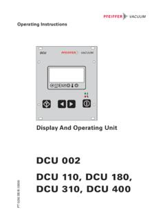
2 The display will change to the Sync Sync setting is shown as 0o through 9o with 0o being the least aggressive and 9o being the most Sync adjustment has no effect on the Manual Sync Control would be adjusted for individual driver preference or changing road ControlThe Manual Control is located on the front of the Brake Control Unit at the right Manual Control only applies the trailer brakes and would be used during initial setup and in situations where it is desirable to reduce speed the Manual Control is moved to the left, the Control begins to apply the trailer brakes. The further to the left it is moved the harder the brakes are applied until the maximum setting by the Output (Gain) Control is Gain setting will be shown on the display and can be adjusted when using the Manual Manual Control activates all trailer : Some tow vehicles stoplights may also DisplayThe Digital display shows the Gain setting when the Control is activated.
3 It is used to setup and monitor the Brake Control and can be used when trouble For The Installation And Operation Of Electronic Brake ControlFor 2, 4, 6 & 8 Brake applicationsComponents of the Brake ControlA. Output (Gain) ControlB. Sync ControlC. Manual Slide ControlD. Bracket Mounting HolesE. LED DisplayThis Package Includes:(1) Brake Control Unit(1) Mounting Bracket(4) Mounting Screws(1) Warranty CardMaterial Required:10 Ga. wire30 Amp auto-reset circuit breakerAssorted ring terminal & butt connectors4" cable ties (6-10)Tools Required:Assorted end wrenchesDrill with 1/8" bitWire connector crimp toolProbe type circuit testerWire cutter/stripperScrewdriver or 1/4" Nut DriverREAD THIS FIRST:Read and follow all instructions carefully before installing or operating the Brake Control . Keep these instructions with the Brake Control for future reference.
4 2014 Cequent Performance Products, Inc P/N 120065-074 REV A 01/14 For Technical Assistance and Warranty Informationcall: 1-888-785-5832 or & ControlsBlack: Vehicle PowerRed: Stop LightWhite: Vehicle GroundBlue: Trailer BrakesBlueWhiteBlackRedSync ControlMore Aggressive Braking (+)Less Aggressive Braking (-)Output (Gain) ControlMore Output (+)Less Output (-)Output / Sync DisplayManual ControlSlide To Apply BrakesSingle DecimalControl ActivatedNo Trailer ConnectedOutput (Gain) DisplayControl ActivatedTrailer ConnectedSync DisplayBrake Pedal PushedSync Control ActivatedTrailer ConnectedDisplay ExamplesOutput (Gain) ControlThe Output (Gain) Control establishes the maximum amount of power available to the trailer the Gain is increased more power will be available to the brakes when the Brake pedal is pressed or the Manual Control is Output (Gain)
5 Control would be adjusted during initial setup, when trailer load changes, when different trailers are used or to adjust for a change in road Gain setting is shown on the digital display when a trailer is connected and the Brake pedal is pressed or the Manual Control is Gain setting is shown as 0 through 10 with 0 being the minimum and 10 the Adjustments:With the trailer connected press and hold the Brake pedal, the Display will show the Gain to approx. by pushing the Gain button up or down as still holding the Brake pedal press either Sync button. The display will change to the Sync to 4o by pressing the Sync button (+ or ) as DriveIn an open area, such as a large parking lot, Drive forward and apply the trailer brakes using the Manual the trailer brakes are weak adjust the Output (Gain) Control the trailer brakes jerk or lockup adjust the Output (Gain) Control this step until firm braking is felt with out jerking or the Gain is set, Drive forward and press the Brake pedal, the tow vehicle and trailer should make a smooth the stop seems slow and more aggressive braking is desired, push the Sync Up (+) button while holding the Brake the stop seems too aggressive press the Sync Down (-)
6 Button while holding the Brake making a Sync adjustment the Display will show the setting until the Brake pedal is several stops at various speeds and adjust the Sync until stops are smooth and firm. Slight adjustment of the Output (Gain) Control may also be : If any problems occur during Setup refer to the Trouble Shooting section of these TipsLight pressure on the Brake pedal will activate the trailer s brakes with no effect on the tow vehicle s brakes. This is useful for gradual slowing on steep grades or before adjustment of the Sync and Output controls may be necessary to correct for changing road conditions, trailer loading, Brake wear, and/or driver some vehicles, operating the Brake Control s Manual Control will not disengage "Cruise Control ".When Towing (in most applications) with Hazard Flashers on the Digital Display will flash with the Hazard Flashers.
7 If the Brake Control is set aggressively pulsing may be felt in the trailer of a Pulse Preventor will isolate the Brake Control from the flashers and eliminate the flash/pulse Chart: Test Without Trailer FirstConditionDisplayProbable CausesPossible SolutionNo Trailer Brakes, Pedal or ManualDecimal point does not light when Brake pedal or Manual Control is usedNo power to Control , no ground, reversed black and white wires, circuit breaker blownCheck and repair connections, refer to "wiring" sectionDecimal point does not light when Brake pedal is pushed does light with manualNo connection or incorrect connection at stoplight switch, blown fuse in stoplight circuitCheck and repair connections, refer to "wiring" section, check stoplight circuitDecimal on all the timeRed wire connected to the wrong side of the stoplight switch or to wrong switch (cruise Control )
8 Check and repair connections, refer to "wiring" sectionDisplay shows output SettingBrake Control unit miswiredCheck and repair connections, refer to "wiring" sectionDisplay shows OL when activatedShort in blue wire circuitLocate and correct shortDisplay shows ErInternal Brake Control problemReturn unit to dealer for evaluationWith Trailer ConnectedNo trailer brakes, pedal or manualNo connection between Brake Control and brakes - blue wire circuitConfirm connection to trailer connector, confirm connector terminal positions, check trailerNo trailer brakes, pedal or manualMiswired trailer connectorConfirm trailer connector terminal positionsNo trailer brakes, pedal or manualShort or overload in trailer brakesTrouble shoot trailer Brake circuit per Brake manufacturer s instructionsNo trailer brakes, pedal or manualInternal Brake Control problemReturn unit to dealer for evaluationWeak or no trailer brakesMiswired trailer connector Output (Gain) setting too lowCheck and correct connector wire positions Increase Output (Gain) ControlTrailer brakes on all the timeMiswired trailer connectorCheck and correct connector wire positionsPedalManualBlankDecimal OnlyOutput SettingFlashing OLErrorDecimal OnlyOutput SettingFlashing OLErrorOutput SettingBlankInstructions d installation et d utilisation de la commande de freins lectroniquePour applications 2, 4, 6 et 8 freinsComposants de la commande de freinsA.
9 Commande de gain de sortieB. Commande de synchronisationC. Commande glissi re manuelleD. Trous de montage du supportE. Afficheur DELL emballage contient :(1) Unit de commande de frein(1) Support de montage(4) Vis de montage(1) Fiche de garantieMat riel requis :Fil calibre 10 Disjoncteur r enclenchement automatique de 30 amp resCosse anneau et connecteur d about appari sAttaches de c ble 4 po (6-10)Outils requis :Cl s ouvertes appropri esPerceuse avec foret 1/8 poOutil de sertissage pour connexion de filsMultim tre pointe de toucheOutil couper et d nuder les filsTournevis ou tournevis douille 1/4 poLISEZ CECI EN PREMIER :Il importe de lire ou de suivre attentivement toutes les consignes avant de poser ou d utiliser la commande de freins. Ces consignes doivent tre conserv es avec la commande de freins pour consultation future. 2014 Cequent Performance Products, Inc P/N 120065-074 REV A 01/14 Pour de l assistance technique ou des informations concernant la garantie, pri re de composer le : 1-888-785-5832 ou visiter le :S assurer que la zone derri re le panneau est libre avant de le support comme guide pour marquer l emplacement des deux (2) trous de 1/8 po (dia.)
10 Et poser le support l aide des vis la commande de freins sur le support l aide des deux (2) vis Choisir un emplacement de montage appropri . A) L appareil doit tre mont d une fa on s curitaire sur une surface solide. B) Le conducteur doit tre en mesure d atteindre l appareil facilement. C) La zone derri re la surface de montage doit tre exempte d objets risque d Tenir le support de montage dans la position choisie et marquer les emplacements des trous travers les fentes du l aide d un foret de 1/8 po, percer les trous aux emplacements marqu l aide d un tournevis ou d un tournevis douille 1/4 po, fixer le support en place l aide de deux (2) vis autotaraudeuses (fournies). Veiller ne pas fausser les trous en serrant Monter la commande de freins sur le support l aide des deux (2) autres vis autotaraudeuses, comme illustr.

![3 b ], B D q 3 b.I ], A q C Typical Boost Settings For ...](/cache/preview/a/3/e/6/a/2/8/d/thumb-a3e6a28de41c190078e312ca74651b92.jpg)

