Transcription of CONNECTOR AMPLIFIER FOR PROPORTIONAL …
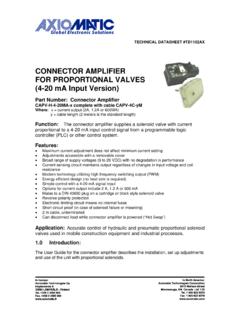
1 TECHNICAL DATASHEET #TD1101AX CONNECTOR AMPLIFIER FOR PROPORTIONAL VALVES (0-10 VDC Input Version) Part No.: CAPV-H-10V-x complete with cable CAPV-S7C-yM Where: x = current output (2A, or 600MA) y = cable length (2 meters is the standard length) Function: The CONNECTOR AMPLIFIER supplies a solenoid valve with current PROPORTIONAL to an input control (0-10 VDC or 0-20 mA). Features: Maximum current adjustment does not affect minimum current setting Adjustments accessible with a removable cover Broad range of supply voltage (9 to 28 VDC) with no degradation in performance Current sensing circuit maintains output regardless of changes in input voltage and coil resistance Modern technology utilizing high frequency switching output (PWM) Energy efficient design (no heat sink is required)
2 Simple control with 0-10 VDC or 0-20 mA signal inputs Options for current output include 2 A, A or 600 mA Mates to a DIN 43650 plug on a cartridge or block style solenoid valve Electronic limiting circuit means no internal fuses Short circuit proof (in case of solenoid failure or miswiring) Reverse polarity protection IP67 weather resistance CE certified for EMC Can disconnect load while unit is powered ( Hot Swap ) Application: Accurate control of hydraulic and pneumatic PROPORTIONAL solenoid valves used in mobile construction equipment and industrial processes. 2 Description: The 0-10 V CONNECTOR AMPLIFIER simplifies control of PROPORTIONAL solenoids by supplying a current PROPORTIONAL to an input control (0-10 V or 0-20 mA).
3 It accepts power supply voltages from 9 to 28 VDC. This linear solenoid driver utilizes high frequency switching output (PWM) to provide a DC current output. The options for maximum current output include 2 A, A or 600 mA. A current sensing circuit maintains output current regardless of changes in input voltage and coil resistance. The user can adjust maximum and minimum current. Ramp time, dither frequency and amplitude can also be adjusted to match the application. The unit is available with a DIN 43650 connection to mount directly on the coil. Other versions are available with 4-20 mA or 0-5 V (including 0-20 mA and 10K potentiometer) inputs. A remote mount version is housed in a rugged metal box.
4 3 Technical Specifications: All specifications typical at nominal input voltage and 25 C unless otherwise specified. General Specifications Operating conditions Storage temperature -40 to +85 C (-40 to 185 F) 0 to 85% relative humidity -50 to 125 C (-58 to 257 F) Weight lbs. ( kg) Electromagnetic compatibility (EMC) Emission EN 50081-2; Immunity EN 50082-2 Approvals CE Electrical connection DIN 43650 plug and 2 metres jacketed cable (2 conductors 18 AWG, 5 conductors 24 AWG) (Remote mount version with cable available) Protection class IP67 when correctly installed with lid, o-ring, washer and base gasket Dimensions in mm/inches (excluding cable) Length L1 L2 L3 Width = L3 Height H1 Electrical Specifications Operating voltage (power supply requirement) 9 to 28 VDC (UL approved range)
5 Accepts up to a maximum of 32 VDC Control input signal options 0-10 VDC voltage signal or 0-20 mA current signal or 10K potentiometer with external power supply provided by customer (4-20mA or 0-5 VDC/0-20mA/10K potentiometer control input versions are also available.) Input resistance Voltage mode: 125K Ohms Current mode: 50 Ohms Range of maximum output current 2 A ( A and 600 mA versions available) Solenoid resistance selection (nominal) Nominal resistance of solenoid coil should comply with: Rcoil < (Vpower supply - V)/I-max Note 1: For proper operation of the AMPLIFIER , match power supply voltage with rating of solenoid coil. Operating the AMPLIFIER with a supply voltage lower than the solenoid rated voltage may result in reduced maximum current output.
6 Note 2: The coil should have no polarity or protection diodes for proper operation of the device. Note 3: The maximum current output of the AMPLIFIER should not exceed the current rating of the solenoid coil. 4 Adjustments Minimum current setting 0 to A (for 2 A output model) 0 to A (for A output model) 0 to 150 mA (for 600 mA output model) Maximum current setting to A (for 2 A output model) to A (for A output model) 180 to 600 mA (for 600 mA output model) Current ramp time - 5 sec. independent Dither amplitude Current dither frequency 0 to 10% of rated maximum current 70 to 350 Hz ( 10% of full scale) Installation Procedures: Precautions Against Leaks From The Environment Ensure the transparent lid is firmly in place.
7 Ensure the brown rubber base gasket is in place, providing a seal between the CONNECTOR AMPLIFIER and the plug on the valve. The mounting screw should be flush with the top of the lid with the o-ring and washer in place. Tighten the screw to make a firm connection to the valve with a Phillips #2 screwdriver. Necessary Equipment PROPORTIONAL Valve Controller/ AMPLIFIER Cartridge or Block PROPORTIONAL Solenoid Valve ready to accept a DIN 43650 plug Hydraulic power source and load circuit Power Supply (9 to 28 VDC) DC voltmeter (optional) Choice of Inputs: 0-10 VDC voltage or 0-20 mA current signal or 10K potentiometer with external power supply External fusing recommended (3A) Installation Steps Supply voltage should be between 9 and 28 VDC.
8 Excess voltage will damage the unit. Match the power supply voltage with the voltage rating of the solenoid coil. Operating the controller/ AMPLIFIER with a supply voltage lower than the solenoid rated voltage may result in reduced maximum current output. The maximum current output of the AMPLIFIER should not exceed the current rating of the solenoid coil. The coil should have no polarity or protection diodes for proper operation of the device. Do not install the unit near high voltage relays or other sources of electrical interference. Connect the power supply, input signal and valve solenoid as shown below and in Section Put isolation sleeves on any unused wires for the input signal.
9 Set the input signal to the maximum level and confirm it is operating properly. Wiring Connections Connect the cable conductors to the power supply and input signal as follows. For Either 0-20 mA or 0-10 VDC Control: Turn ramp screws fully counterclockwise to eliminate ramping. Use I-Min. screw to set up minimum speed with minimum control input. Use I-Max. screw to set maximum speed with 100% of control input. For 10K Potentiometer Control: See diagram below. Enable: When Enable is connected to the -ve power supply, the unit will be disabled. When Enable is left open or connected to the +ve power supply, the unit is enabled. Refer to page 2 (block diagram) for an alternative method of connecting a current loop transmitter to provide a current control signal input.
10 In this method, the current loop transmitter receives power from the power supply powering the AMPLIFIER . The transmitter is connected to the AMPLIFIER s +power supply input wire and the +0 to 20mA input wire. This method does not use the 0 to 20mA input signal wire connection. Set Up Adjustment Procedures: The location of the trim pots for the set up adjustments are shown in Section WARNING: The operator must ensure that the operation of the valve within the full scale of the control function will not cause hazards, while performing set up adjustments to the CONNECTOR AMPLIFIER . Preparation Ensure that the CONNECTOR AMPLIFIER is connected to an operating PROPORTIONAL valve.