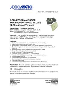
Transcription of TECHNICAL DATASHEET #TD1404AX PWM …
1 TECHNICAL DATASHEET # td1404ax PWM CONTROLLED SOLENOID DRIVER (PWM Input, or 2A Output, Metal Box or PCB) PCB Board - P/N: PWMC-PCB-2A, Packaged Driver (metal box with m (5 ft.) cable) - P/N: , Application: Diesel Engine Control Module Interface For Hydraulic Fan Drive Applications - The PWM Controller interfaces to the PWM signal provided by a diesel engine control module and drives a proportional solenoid valve in a hydraulic fan drive circuit PLC interface in Mobile Equipment and Industrial Automation Applications The PWM Controller accepts a PWM signal from a PLC and controls a proportional solenoid valve in a variety of applications. Description: The PWM Controlled Solenoid Driver supplies a proportional solenoid with current proportional to a digital pulse width modulated (PWM) input signal.
2 It accepts power supply voltages from 9 to 32 VDC. This linear solenoid driver utilizes high frequency switching output (PWM) to provide a DC current output of 2 Amps ( version available). A current sensing circuit maintains output current regardless of changes in input voltage and coil resistance. The user can adjust the zero setting, maximum output current, dither frequency and dither level as well as independent rising and falling ramps to suit their application. A system of LED's indicates output power level, input level and power on/off. The unit is available as a stand alone PCB Board or as a Packaged Driver enclosed in an IP67 rated metal housing with m (5 ft.) of cable. The circuit board is conformal coated.
3 The metal box or PCB is designed for remote mounting. A DIN rail mount version is also available. The metal box and DIN rail versions comply with CE directives for EMC. Features: Stand alone PCB Board or enclosed in a metal housing with cable DIN rail mount version available Maximum current adjustment does not affect zero setting Current sensing circuit maintains output current regardless of input voltage and coil resistance Broad range of supply voltages (9 to 32 VDC) with no degradation in performance Modern technology utilizing high frequency switching output (PWM) Energy efficient design (no heat sink is required) Accepts a PWM input from a PLC or other source Options for maximum current output include 2 A and A LED indication of output power level, input level and power on/off Electronic limiting circuit means no internal fuses Short circuit proof (in case of solenoid failure or miswiring) CE certified for EMC (metal box and DIN rail versions)
4 IP67 rating (metal box version) Reverse polarity protected Filter eliminates electrical noise 2 Block Diagram TECHNICAL Specifications: Typical at nominal input voltage and 25 degrees C unless otherwise specified. Input Specifications: PWM Non-isolated Accepts PWM inputs from 250 to 5,000 Hz For PWM inputs <250 Hz, contact the manufacturer for a factory modification. PWM range 5-95% (Other ranges can be specified.) Input Voltage Low < High > (50V max.) TTL and CMOS compatible Input Impedance 200kOhm Output Specifications: Maximum Current Output 2A or (Outputs up to 2A are available. contact manufacturer) PWM Output High frequency switching Short Circuit Protection Provided 3 General Specifications: Power Supply 9-32 VDC Transient protection is provided. Reverse Polarity Protection Provided EMI Compliance Emission EN 50081-2 immunity EN 50082-2 Approvals CE (metal box and DIN rail versions) Operating Conditions -40 to 85 degrees C (-40 to 185 degrees F) Protection Metal box version IP67 Electrical connection PCB version: 10 screw terminals accept 16-20 AWG wire for the power conductors and 18-24 AWG wire for the signal conductors Metal box version: Unterminated cable - 5 ft.
5 ( ) standard length 1 twisted quad AWG 18 ( mm2) for power and output conductors plus 5 insulated wires AWG 24 ( mm2) for signal conductors plus drain wire Enable When Enable is connected to the -ve power supply, the unit will be disabled. When Enable is left open or connected to the +ve power supply, the unit is enabled. Dimensions - PCB Board x x mm (W x D x H) x x inches Dimensions - Packaged Driver with cable x x mm x x inches (W x D x H excluding grommet and cable) Note 1: For proper operation, match the power supply voltage with rating of solenoid coil. Operating the driver with a supply voltage lower than the solenoid rated voltage may result in reduced maximum current output. Note 2: The coil should have no polarity or protection diodes for proper operation of the device.
6 Note 3: The max. current output of the driver should not exceed the current rating of the solenoid coil. 4 Adjustments: Range of Adjustment (single turn trim pots) Factory Setting Dither Frequency 70 to 350 Hz (+/- 10% of full scale) Dither waveform is triangular. CW = increasing Set dither frequency to match solenoid rating. Minimum (70 Hz) (CCW) Dither Level 0 to 10% of maximum current CW = increasing Choose the smallest effective dither amplitude. This is achieved when small changes in input register similar changes in current output. Minimum (0%) (CCW) Zero CW = increasing Adjustment range of Zero trim pot is 0 to 130 mA. (5% PWM input provides 0A output, with Span setting at max. value.) Factory calibrated (5% PWM input provides 0A output) I max CW = increasing Adjustment range is to (2A version).
7 Adjustment range is to ( version). (95% PWM input provides desired maximum output) Maximum (depends on rating) (CW) Rising Edge (Ramp) to seconds independent CW = increasing seconds (CCW) Falling Edge (Ramp) to seconds independent CW = increasing seconds (CCW) CW = clockwise, CCW = counterclockwise Specifications are subject to update without notice. Mounting Instructions and Wiring Connections: For stand alone PCB Boards: Mounting the PCB board The board will accommodate #6 size mounting screws (not supplied). Connecting to the screw terminals on the board Use a cable to connect to the PCB board with each wire stripped to mm (1/4 inch) and the shield (jacket) stripped to permit splaying of the wires in the screw terminals without tension. The exposed ground shield wire should have a heat shrink placed around the wire as a precautionary measure.
8 Reference the label (included with the board) for the pin out connections of the screw terminals. To connect the cable to the board, loosen each screw terminal, insert the pre-tinned wire and tighten with a jeweller's sized screwdriver. Take care to position the ground shield wire away from the PCB Board. 5 For Packaged Drivers (Metal Box with Cable): Mounting the housing Mount the housing using four #10-32 bolts or screws. Connecting the cable Connect the cable to the load, power supply and input signal as shown. For PWM Control: Turning the ramp trim pots fully counterclockwise will eliminate ramping. The unit is shipped from the factory calibrated for 0A output when 5% PWM is applied and full scale output when 95% PWM is applied. If an offset is required, use the Zero trimpot to provide the current necessary to overcome the valve deadband.
9 Use the I-Max. trim pot to set the desired maximum current output with 95% PWM input. Refer to Calibration Steps. Enable: When Enable is connected to the -ve power supply, the unit will be disabled. When Enable is left open or connected to the +ve power supply, the unit is enabled. Adjustment Details: Adjustments are accessible by loosening the four screws on the lid of the housing and removing the lid. Ensure that the unit is connected to an operating proportional valve. Use a Phillips #1 screwdriver to make adjustments to the trim pots. The following settings represent a typical set up. Conditions will vary for other set up scenarios. Trim pots are single turn. Use a Phillips #1 screwdriver to adjust the single turn trim pots. Trim Pots Range of Adjustment Setting from Factory Zero 0 to 130 mA (5% PWM input provides 0A output, with Span setting at max.)
10 Value.) Factory calibrated (5% PWM input provides 0A output) Maximum Current Setting (I-max.) 2A output: 600 to 2000 mA output: 360 to 1200 mA (95% PWM input provides desired maximum output.) Maximum (CW) Ramp Time (Rising and Falling Edge) to 5 seconds independent seconds (CCW) Dither Level (Amplitude) 0 to 10% of rated maximum current 0% (CCW) Dither Frequency 70 to 350 Hz ( 10%) Minimum (CCW) 6 Calibration Steps Setting the Output Current Current output is measured by an ammeter set up in series with the driver and the load. Connect the Solenoid + output to the + terminal on the Ammeter and the Ammeter to the Solenoid. Connect the Solenoid - output to the Solenoid. The maximum current setting is adjusted to meet the customer s working pressure or flow range to the full scale signal input range.