Transcription of TECHNICAL DATASHEET #TDAX030500 4 Analog …
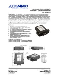
1 TECHNICAL DATASHEET #TDAX030500 4 Analog Signal Outputs CAN Controller SAE J1939 with Electronic Assistant P/N: AX030500 Distributed I/O for Engine Control Systems Features: 4 independent Analog signal outputs (voltage or current) User selectable output range from +/-10V or +/-20 mA, including: 0-5V; 0-10V; +/-5V; +/-10V; 0-20mA; 4-20 mA; and +/-20mA. 12V/24V/48 VDC input power (nominal) with rugged surge protection Galvanic isolation between power supply and Analog signal outputs 1 CAN (SAE J1939), CANopen on request Rugged IP67 packaging and connectors Vibration compliant for engine applications Electronic Assistant runs on a Windows operating system for user configuration and programming.
2 An Axiomatic USB-CAN converter links the PC to the CAN bus. Applications: Distributed controls for power generation, co-generation, stationary power Distributed controls for commercial vehicles, off-highway equipment, industrial equipment, etc. Ordering Part Numbers: SAE J1939 Controller: For baud rate, refer to the table below for the appropriate P/N. Model P/N Baud Rate Standard Reference AX030500 250 kBit/s J1939/11, J1939/15. AX030502 500 kBit/s J1939/14. New standard AX030503 1 Mbit/s Non-standard Accessories: PL-DTM06-12SA Mating Plug Kit (1 DTM06-12S, 1 WM12S, 12 contacts, FG- IOCTRL-20) Electronic Assistant Configuration KIT.
3 AX070502 TDAX030500 2 Block Diagram TDAX030500 3 TECHNICAL Specifications: Input Specifications Power supply Input - Nominal 12V, 24V or 48 VDC nominal ( VDC power supply range) Protection Surge and reverse polarity protection are provided.
4 Isolation A transformer power supply provides galvanic isolation between the power supply input and the Analog signal outputs. Input CAN Messages, SAE J1939 {CANopen (model AX030501) available on request} The CAN signal can be filtered to accept messages from a single address on the network permitting a link to a specific ECU. The Electronic Assistant (EA) is used to set up CAN signal acquisition and processing algorithms. Output Specifications CAN The controller can send a single frame application specific CAN message to the network continuously or on request. Using the EA, the user can configure this feature.
5 Analog Outputs Up to 4 Analog signal outputs are selectable by the user. Refer to Table Ground Connection 3 Analog GND connections are provided. They are connected together internally. Protection for Output + Terminal Fully protected against short circuit to ground and short circuit to power supply rail. Unit will fail safe in the case of a short circuit condition, self-recovering when the short is removed. Table - Outputs Analog Outputs Up to 4 Analog signal outputs are available. Using the Electronic Assistant , the user selects: the output mode (voltage or current); and the minimum and maximum values for the output signal from the +/-10V or +/-20 mA range.
6 Standard Analog signal ranges are supported, including: 0-5V; 0-10V; +/-5V; +/-10V; 0-20mA; 4-20 mA; and +/-20mA. The outputs can be globally enabled or disabled. Output Accuracy Output Resolution (>12 bit) Control Logic From the software perspective, the controller consists of a set of internal functional blocks, which can be individually programmed and arbitrarily connected together to achieve the required system functionality, see Figure 1. Each functional block is absolutely independent and has its own set of programmable parameters, or setpoints. The setpoints can be viewed and changed through CAN using the Electronic Assistant.
7 There are two types of the controller functional blocks. One type represents the controller hardware resources, for example the Analog signal output block. The other type is purely logical these functional blocks are included to program the user defined functionality of the controller. The number and functional diversity of these functional blocks are only limited by the system resources of the internal microcontroller. They can be added or modified on the customer s request to accommodate user-specific requirements. The user can build virtually any type of a custom control by logically connecting inputs and outputs of the functional blocks.
8 This approach gives the user an absolute freedom of customization and an ability to fully utilize the controller hardware resources in a user s application. TDAX030500 4 Figure Controller Internal Structure. Depending on the block functionality, a functional block can have: logical inputs, logical outputs or any combinations of them. The connection between logical inputs and outputs is defined by logical input setpoints.
9 The following rules apply: A logical input can be connected to any logical output using a logical input setpoint. Two or more logical inputs can be connected to one logical output. Logical outputs do not have their own setpoints controlling their connectivity. They can only be chosen as signal sources by logical inputs. Each functional block of the controller is presented by its own folder in the Setpoint File root folder in the Electronic Assistant . Analog Signal Output Global ParametersBinary Function CAN Output Message J1939 CAN Bus Logical Logical 4 Analog Signal Outputs Analog Signal Output Global Control CAN Input Signal As an example, the logical output of the CAN Input Signal functional block is connected to the logical input of the Analog Signal Output functional block, providing a direct path for the CAN input signal to the controller signal output.
10 The default controller configuration can be different from the one shown here. EN TDAX030500 5 General Specifications Microprocessor STM32, 32-bit, 128 KByte flash program memory Control Logic Standard embedded software is provided. Refer to Figure (Application-specific control logic or factory programmed setpoints are available on request.) Monitoring and Troubleshooting The controller can also transmit a CAN application message carrying signals internally generated by the controller.