Transcription of Contents
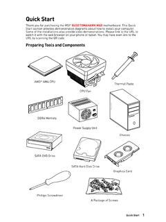
1 1< 1>ContentsContentsSafety Information ..2 Specifications ..3 Rear I/O Panel ..8 LAN Port LED Status Table ..8 Overview of Components ..9 CPU Socket ..10 DIMM : Slot (Key M) ..11M2_2: Slot (Key E) ..12 PCI_E1~2: PCIe Expansion Slots ..12 SATA1~4: SATA 6Gb/s Connectors ..13 JAUD1: Front Audio Connector ..13 JFP1, JFP2: Front Panel Connectors ..14 ATX_PWR1, CPU_PWR1: Power Connectors ..15 JUSB1: USB Connector ..16 JUSB2: USB Gen 1 5 Gbps Connector ..16 CPU_FAN1, SYS_FAN1: Fan Connectors ..17 JTPM1: TPM Module Connector ..17 JCI1: Chassis Intrusion Connector ..18 JCOM1: Serial Port Connector ..18 JBAT1: Clear CMOS (Reset BIOS) Jumper ..19EZ Debug LED ..19 Installing OS, Drivers & MSI Center ..20 Installing Windows 10 ..20 Installing Drivers ..20 MSI Center ..20 UEFI BIOS ..21 BIOS Setup ..22 Entering BIOS Setup ..22 BIOS User guide ..22 Resetting BIOS ..23 Updating you for purchasing the MSI H510M PRO/ H510M-A PRO/H510M BOMBER/ B560M PRO-E/ B560M PLUS/ B560M-X motherboard.
2 This User guide gives information about board layout, component overview, BIOS setup and software InformationSafety Information The components included in this package are prone to damage from electrostatic discharge (ESD). Please adhere to the following instructions to ensure successful computer assembly. Ensure that all components are securely connected. Loose connections may cause the computer to not recognize a component or fail to start. Hold the motherboard by the edges to avoid touching sensitive components. It is recommended to wear an electrostatic discharge (ESD) wrist strap when handling the motherboard to prevent electrostatic damage. If an ESD wrist strap is not available, discharge yourself of static electricity by touching another metal object before handling the motherboard. Store the motherboard in an electrostatic shielding container or on an anti-static pad whenever the motherboard is not installed.
3 Before turning on the computer, ensure that there are no loose screws or metal components on the motherboard or anywhere within the computer case. Do not boot the computer before installation is completed. This could cause permanent damage to the components as well as injury to the user. If you need help during any installation step, please consult a certified computer technician. Always turn off the power supply and unplug the power cord from the power outlet before installing or removing any computer component. Keep this user guide for future reference. Keep this motherboard away from humidity. Make sure that your electrical outlet provides the same voltage as is indicated on the PSU, before connecting the PSU to the electrical outlet. Place the power cord such a way that people can not step on it. Do not place anything over the power cord. All cautions and warnings on the motherboard should be noted.
4 If any of the following situations arises, get the motherboard checked by service personnel: Liquid has penetrated into the computer. The motherboard has been exposed to moisture. The motherboard does not work well or you can not get it work according to user guide . The motherboard has been dropped and damaged. The motherboard has obvious sign of breakage. Do not leave this motherboard in an environment above 60 C (140 F), it may damage the InformationSpecificationsSpecificationsC PU Supports 10th Gen Intel Core Processors, 11th Gen Intel Core Processors, Pentium Gold and Celeron Processors Processor socket LGA1200* Please go to for compatibility H510/ B560 chipsetMemory 2x DDR4 memory slots, support up to 64GB* Supports 1R 2133/ 2666/ 2933 MHz for 10th Gen Intel CPU (by JEDEC & POR) Supports 1R 2133/ 2666/ 2933/ 3200 MHz for 11th Gen Intel CPU (by JEDEC & POR) Max overclocking frequency (For B560M PRO-E/ B560M PLUS/ B560M-X).
5 1 DPC 1R Max speed up to 4800 MHz 1 DPC 2R Max speed up to 4600+ MHz Supports Dual-Channel mode Supports non-ECC, un-buffered memory Supports Intel Extreme Memory Profile (XMP)* Please refer to for more information on compatible Slots 1x PCIe x16 slot (From CPU) Supports up to PCIe for 11th Gen Intel CPU Supports up to PCIe for 10th Gen Intel CPU 1x PCIe x1 slot (From PCH) 1x slot (Key E) (For H510M PRO/ H510M-A PRO/ H510M BOMBER) M2_2 supports PCIe Wi-Fi module onlyContinued on next page4 SpecificationsContinued from previous pageOnboard Graphics 1x HDMI with HDR port, supports a maximum resolution of 4K 60Hz*/** 1x VGA port, supports a maximum resolution of 2048x1536 60Hz, 1920x1200 60Hz (For H510M PRO/ H510M-A PRO/ H510M BOMBER/ B560M PRO-E/ B560M-X)* 1x DisplayPort port, supports a maximum resolution of 4K 60Hz (For H510M PRO)*/** Available only on processors featuring integrated graphics.
6 ** Graphics specifications may vary depending on the CPU ALC892/ ALC897 Codec High Definition AudioLAN1x Intel I219V 1 Gbps LAN controllerStorage 4x SATA 6Gb/s ports (From H510/ B560 Chipset) 1x slot (Key M) (For H510M PRO/ H510M-A PRO/ H510M BOMBER/ B560M PRO-E/ B560M PLUS) M2_1 slot (From H510/ B560 Chipset)* Supports up to PCIe x4 Supports SATA up to 6Gb/s Supports 2242/ 2260/ 2280 storage devices* SATA4 will be unavailable when installing SATA SSD in the M2_1 Intel H510/ B560 Chipset 4x USB Gen 1 5 Gbps ports (2 Type-A ports on the back panel, 2 ports available through the internal USB connector) 6x USB ports (4 Type-A ports on the back panel(hub-GL850G), 2 ports available through the internal USB connector)Continued on next page5 SpecificationsSpecificationsContinued from previous pageInternal Connectors 1x 24-pin ATX main power connector 1x 8-pin ATX 12V power connector 4x SATA 6Gb/s connectors 1x USB Gen 1 5 Gbps connector (supports additional 2 USB Gen 1 5 Gbps ports) 1x USB connector (supports additional 2 USB ports) 1x 4-pin CPU fan connector 1x 4-pin system fan connector 1x front panel audio connector 2x system panel connectors 1x serial port connector 1x Chassis Intrusion connector 1x Clear CMOS jumper 1x TPM module connectorBack Panel Connectors 1x PS/2 keyboard/ mouse combo port 1x VGA port (For H510M PRO/ H510M-A PRO/ H510M BOMBER/ B560M PRO-E/ B560M-X) 1x DisplayPort (For H510M PRO) 1x HDMI port 4x USB ports 2x USB Gen 1 5 Gbps Type-A ports 1x LAN(RJ45) port 3x audio jacksLED Feature 4x EZ Debug LED 1x 4-pin RGB LED connector (For H510M PRO)
7 1x 3-pin RAINBOW LED connector (For H510M PRO)I/O ControllerNUVOTON NCT6687D-M Controller ChipHardware Monitor CPU/System temperature detection CPU/System fan speed detection CPU/System fan speed controlForm Factor mATX Form Factor x in. ( cm x cm)Continued on next page6 SpecificationsContinued from previous pageBIOS Features 1x 256 Mb flash UEFI AMI BIOS ACPI , SMBIOS Multi-languageSoftware MSI Center Intel Extreme Tuning Utility CPU-Z MSI GAMING Google Chrome , Google Toolbar, Google Drive Norton Internet Security SolutionMSI Center Features LAN Manager Mystic Light (For H510M PRO) User Scenario Hardware Monitor Frozr AI Cooling True Color Live Update Speed Up Super ChargerContinued on next page7 SpecificationsSpecificationsContinued from previous pageSpecial Features Audio Audio Boost Network LAN Manager Cooling Smart Fan Control LED Mystic Light Extension(RGB) (For H510M PRO) Mystic Light Extension (RAINBOW) (For H510M PRO) Mystic light SYNC (For H510M PRO) EZ LED Control (For H510M PRO)
8 EZ DEBUG LED Performance Lightning Gen 4 PCI-E Slot DDR4 Boost Core Boost 2oz Copper thickened PCB Protection PCI-E Steel Armor Experience MSI Center Frozr AI Cooling Click BIOS 5 CPU Cooler Tuning8 Rear I/O PanelLink/ Activity LEDS tatusDescriptionOffNo linkYellowLinkedBlinkingData activitySpeed LEDS tatusDescriptionOff10 Mbps connectionGreen100/1000 Mbps connectionOrange1 Gbps connectionLAN Port LED Status TableAudio ConfigurationTo configure audio, you have to connect front audio I/O module to JAUD1 connector and follow the below Click on the Realtek HD Audio Manager > Advanced Settings to open the dialog Select Mute the rear output device, when a front headphone plugged Plug your speakers to audio jacks on rear and front I/O panel. When you plug into a device at an audio jack, a dialogue window will pop up asking you which device is current I/O PanelPS/2 Mouse/ KeyboardLANUSB Type-AUSB Gen 1 5 Gbps Type-ADisplayPort(For H510M PRO)VGA Port(For H510M PRO/ H510M-A PRO/ H510M BOMBER/ B560M PRO-E/ B560M-X)USB Type-ALine-inLine-outMIC9 Rear I/O PanelOverview of ComponentsLine-outOverview of Components* Distance from the center of the CPU to the nearest DIMM slot.
9 BAT1 SYS_FAN1 CPU_FAN1 CPU SocketM2_1(optional)M2_2(optional)PCI_E2 PCI_E1 DIMMA1 DIMMB1 JTPM1 SATA 3 4 SATA2 SATA1 JAUD1 JRGB1(optional)JRAINBOW1(optional)JBAT1 ATX_PWR1EZ Debug *10 Overview of ComponentsCPU SocketPlease install the CPU into the CPU socket as shown below. Important Always unplug the power cord from the power outlet before installing or removing the CPU. Please retain the CPU protective cap after installing the processor. MSI will deal with Return Merchandise Authorization (RMA) requests if only the motherboard comes with the protective cap on the CPU socket. When installing a CPU, always remember to install a CPU heatsink. A CPU heatsink is necessary to prevent overheating and maintain system stability. Confirm that the CPU heatsink has formed a tight seal with the CPU before booting your system. Overheating can seriously damage the CPU and motherboard. Always make sure the cooling fans work properly to protect the CPU from overheating.
10 Be sure to apply an even layer of thermal paste (or thermal tape) between the CPU and the heatsink to enhance heat dissipation. Whenever the CPU is not installed, always protect the CPU socket pins by covering the socket with the plastic cap. If you purchased a separate CPU and heatsink/ cooler, Please refer to the docu-mentation in the heatsink/ cooler package for more details about of ComponentsOverview of ComponentsDIMM SlotsPlease install the memory module into the DIMM slot as shown Important To ensure system stability for Dual channel mode, memory modules must be of the same type, number and density. Some memory modules may operate at a lower frequency than the marked value when overclocking due to the memory frequency operates dependent on its Serial Presence Detect (SPD). Go to BIOS and find the DRAM Frequency to set the memory frequency if you want to operate the memory at the marked or at a higher frequency.