Transcription of Cree XLamp LEDs
1 CLD-AP134 rev 1F. Support document Cree XLamp leds Solder Joint Reliability Study Table of Contents Executive Summary Executive Commercial applications of high-power leds have dramatically increased over the last several years because of leds ' high Assembly of Materials and reliability, long lifetime and energy savings potential. There are Test Board high expectations for LED-based luminaires for commercial, MCPCB indoor, outdoor and residential applications. LED-based Solder luminaires are increasingly required to meet the reliability Solder standards and ENERGY STAR requirements for long term Assembly Process lumen maintenance (L70 > 35,000 hours)1 [1].
2 Solder Reflow The reliability of the solder joint between the LED package X-ray and printed circuit board (PCB) is very critical in ensuring the Thermal Shock overall reliability of an LED lighting fixture. This application note Thermal Shock Test describes a reliability investigation of solder joints for Cree high- Thermal Shock Test power XLamp leds using thermal shock testing. Thermal shock Interpretation of Thermal Shock Failure Data Using is a much more rigorous life test procedure than thermal cycling Weibull tests and causes a significant acceleration in the evolution of Thermal Shock Induced Failure failure mechanisms, thereby precipitating potential failures Solder Joint earlier than thermal cycling tests.
3 Although thermal shock is instructive in identifying the most likely point of system failure under thermal stress, there is no known correlation of thermal shock testing to real world operating environments and these results should not be used as a predictive indicator of system lifetime or failure rates. 1 That is, after 35,000 hours of operation, the luminaire will still deliver 70% of its initial luminous flux. Copyright 2013-2018 Cree, Inc. All rights reserved. The information in this document is subject to change without notice.
4 Cree and XLamp are Cree, Inc. registered trademarks and the Cree logo is a trademark of Cree, Inc. ENERGY STAR is a registered trademark of the Environmental Protection 4600 Silicon Drive Agency. Other trademarks, product, and company names are the property of their respective owners and do not imply specific product and/or vendor Durham, NC 27703. endorsement, sponsorship or association. This document is provided for informational purposes only and is not a warranty or a specification. For USA Tel: + product specifications, please see the data sheets available at For warranty information, please contact Cree Sales at XLamp LED Solder Joint Reliability Introduction The unique advantages offered by high-power leds are driving widespread adoption of this technology in markets previously dominated by traditional lighting technologies.
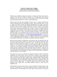
5 One of the major value propositions of LED-based lighting solutions is long-term reliability. Hence, establishing long-term high-reliability performance with relevant data is critical for LED-based lighting applications. Besides the LED chip, a typical LED package consists of various substrate materials, components, and encapsulants which vary with different manufacturers. The three joints whose integrity is critical to ensuring thermal transfer from the junction of the LED to the heat sink are illustrated in Figure 1. 1.
6 LED chip to LED substrate LED chip 2. LED substrate to PCB. LED substrate 3. PCB to heat sink PCB. Heat sink Figure 1: Points critical to ensuring thermal transfer from LED junction to heat sink The LED manufacturer verifies the integrity of the LED chip to LED substrate joint. The PCB and luminaire assembly firm is responsible for verifying the integrity of the other two joints. The integrity of the LED substrate to PCB solder joint is one of the key determinants of long-term lumen maintenance and reliability of LED products.
7 Solder joint reliability not only depends on the solder alloys, but also on the metallization of the LED package and PCB. In addition, the reflow profile also has a significant impact on lead-free solder joint performance since it influences the wetting behavior and microstructure of the solder joint. A damaged or faulty solder joint can cause an open circuit failure that in turn can causes the complete electrical failure of the lamp or luminaire. Thermal shock testing has a much more rapid ramp rate than thermal cycling, thus inflicting much more damage to solder joints.
8 Thermal shock testing results can provide significant insight into the reliability of solder joints [4]. This study uses thermal shock to evaluate the reliability of solder joints for selected high power XLamp LED packages. The reliability of a solder joint is defined as the probability that the solder joint can perform the required function under specified operating conditions for a given time interval. Eutectic Sn63Pb37 solder (63% tin, 37% lead), which was historically the alloy of choice for soldering applications, has been replaced by lead-free solder alloys due to health and environmental concerns.
9 Solder joint failures are a common failure mode observed in electronic packages [2]. The formation of a reliable solder joint depends on several factors such as the ability of the molten solder to rapidly and uniformly wet the surface finish and interact with it to form a consistent intermetallic layer at the interface [3]. The wetting behavior, interface chemistry, and metallurgical microstructure of the solder joint are determined predominantly by the reflow temperature. In addition, overall solder joint reliability is determined by a combination of operating environment and system design.
10 The operating environment determines the temperature extremes which the product must endure, frequency of on/off power cycling and the possibility of mechanical shocks or vibrational stresses [3]. Copyright 2013-2018 Cree, Inc. All rights reserved. The information in this document is subject to change without notice. Cree and XLamp are registered trademarks and the Cree logo is a trademark of Cree, Inc. ENERGY STAR is a registered trademark of the Environmental Protection Agency. Other trademarks, product, and company names are the property of their respective owners and do not imply specific product and/or vendor endorsement, sponsorship or association.