Transcription of Cuti - Metra Online
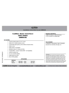
1 CAUTION! All accessories, switches, climate controls panels, and especially air bag indicator lights must be connected before cycling the ignition. Also, do not remove the factory radio with the key in the on position, or while the vehicle is running. TYTO-01 INSTALLATION COPYRIGHT 2017 Metra ELECTRONICS CORPORATION REV. 12/29/17 INSTTYTO-01 INTERFACE FEATURESINTERFACE COMPONENTSTOOLS REQUIRED Cutting tool Crimping tool Tape Connectors (example: butt-connectors, bell caps, etc.)TABLE OF CONTENTSC onnections to be made ..2-3 Installing the TYTO-01 ..3 Testing the TYTO-01 ..3 Toyota amplified interface 2001-up* Provides accessory power (12-volt 10-amp) Used in amplified systems High level speaker input USB updatable Retains balance and fade TYTO-01 interface 16-pin harness with stripped leads 14-pin to 20-pin harness with stripped leads*Visit for up-to-date vehicle specific inside front cover2 APPLICATIONSCONNECTIONS TO BE MADEL exusES330 2004-2006ES300 2002-2003IS300 2002-2005LS430 2001-2006RX330 2004-2006RX350 2007-2009RX400H 2006-2008SC430 2002-2010 Toyota4-Runner (excludes Urban Runner)
2 2003-upAvalon 2005-upCamry 2007-upCorolla 2005-2011FJ Cruiser 2011-upHighlander 2008-upMatrix 2005-2012 Prius 2004-2011 Prius (3rd gen/PHV) 2012-upRav4 2004-upSequoia 2005-upSienna 2004-upSolara 2004-2008 Tacoma 2005-upTundra 2006-upTundra (double cab) 2004-2005 Venza (without NAV) 2009-upVenza (with NAV and separate display) 2013-upYaris 2007-2011 From the 16-pin harness to the aftermarket radio: Connect the White wire to the left front positive speaker. Connect the White/Black wire to the left front negative speaker. Connect the Gray wire to the right front positive speaker. Connect the Gray/Black wire to the right front negative speaker.
3 Connect the Green wire to the radio s left rear positive speaker. Connect the Green/Black wire to the radio s left rear negative speaker. Connect the Purple wire to the radio s right rear positive speaker. Connect the Purple/Black wire to the radio s right rear negative speaker. Connect the Blue/White wire to the amp turn-on/power antenna. Note: The Blue/White wire must be connected or you will not hear sound from the factory amplifier. The following wires on the 16-pin harness will not be used, tape up and disregard: Red, Brown, Light Green, Blue/Pink, Green/Purple, Orange/White Connect the 16-pin harness to the TYTO-01.
4 Continued on the next page323 From the 20-pin harness, to the aftermarket radio: Connect the Yellow wire to the 12-volt battery/memory wire. Connect the Black wire to the ground wire. Connect the Red wire to the accessory /ignition wire. Connect the Orange wire to the illumination wire. Note: If the aftermarket radio does not have an illumination wire, tape up and disregard the Orange wire. Connect the 14-pin harness to the TYTO-01. With all connections completed to the aftermarket radio, plug the 20-pin harness into the vehicles wiring harness. Reconnect the negative battery terminal. Cycle the key, by turning the ignition on for 30 seconds.
5 Then off and on again to test the radio. Turn the ignition on if not already, and then turn the radio on to verify that the radio works. Check balance and fader controls for proper operation. To adjust the overall volume of your audio system, rotate the potentiometer which is located on the 16-pin side of the interface TO BE MADEINSTALLING THE TYTO-01 TESTING THE TYTO-01 KNOWLEDGE IS POWERE nhance your installation and fabrication skills by enrolling in the most recognized and respected mobile electronics school in our onto or call 800-354-6782 for more information and take steps toward a better tomorrow.
6 Metra recommends MECP certified techniciansIMPORTANTIf you are having difficulties with the installation of this product, please call our Tech Support line at 1-800-253-TECH. Before doing so, look over the instructions a second time, and make sure the installation was performed exactly as the instructions are stated. Please have the vehicle apart and ready to perform troubleshooting steps before COPYRIGHT 2017 Metra ELECTRONICS CORPORATION REV. 12/29/17 INSTTYTO-01 INSTALLATION INSTRUCTIONSTYTO-01 PRECAUCI N! Todos los accesorios, interruptores, paneles de controles de clima y especialmente las luces del indicador de las bolsas de aire deben estar conectados antes ciclar la ignici n.
7 Adem s, no quite el radio de f brica con la llave en la posici n o de encendido ni con el veh culo DE INSTALACI COPYRIGHT 2017 Metra ELECTRONICS CORPORATION REV. 12/29/17 INSTTYTO-01 CARACTER STICAS DE LA INTERFASECOMPONENTES DE LA INTERFASEHERRAMIENTAS REQUERIDAS Cortador Pelacables Cinta Conectores (p. ej., conectores a tope, tapas acampanadas, etc.)INDICEC onexiones que se deben hacer ..2-3 Instalaci n del TYTO-01 ..3 Prueba del TYTO-01 ..3 Toyota interfase amplificada 2001 y mas* Provee corriente de accesorio (12 voltios 10 amperes) Se usa en sistemas amplificados Entrada de bocina de alto nivel Actualizable mediante USB Retiene el balance y la intensidad Interfase TYTO-01 Arn s de 16 pins con conectores pelados Arn s de 14 pins a 20 pins con cables pelados* Visite para aplicaciones espec ficas de veh culos dentro de la portada2 APLICACIONESCONEXIONES QUE SE DEBEN HACERL exusES330 2004-2006ES300 2002-2003IS300 2002-2005LS430 2001-2006RX330 2004-2006RX350 2007-2009RX400H 2006-2008SC430 2002-2010 Toyota4-Runner (excluye Urban Runner)
8 2003 y masAvalon 2005 y masCamry 2007 y masCorolla 2005-2011FJ Cruiser 2011 y masHighlander 2008 y masMatrix 2005-2012 Prius 2004-2011 Prius (3rd gen/PHV) 2012 y masRav4 2004 y masSequoia 2005 y masSienna 2004 y masSolara 2004-2008 Tacoma 2005 y masTundra 2006 y masTundra (doble cabina) 2004-2005 Venza (sin NAV) 2009 y masVenza (con NAV y pantalla independiente) 2013 y masYaris 2007-2011 Desde el arn s de 16 pins al radio de mercado secundario: Conecte el cable blanco con la salida positiva de la bocina izquierda del frente. Conecte el cable blanco/negro con la salida negativa de la bocina izquierda del frente.
9 Conecte el cable gris con la salida positiva de la bocina derecha del frente. Conecte el cable gris/negro con la salida negativa de la bocina derecha del frente. Conecte el cable verde con la salida positiva de la bocina trasera izquierda del radio. Conecte el cable verde/negro con la salida negativa de la bocina trasera izquierda del radio. Conecte el cable p rpura con el cable positivo trasero de la bocina. Conecte el cable p rpura/negro con la salida negativa de la bocina trasera derecha del radio. Conecte el cable azul/blanco con el encendido del amp/ antena el ctrica. Nota: El cable azul/blanco debe conectarse para escuchar sonido del amplificador de f brica.
10 No se usar n los siguientes cables en el arn s de 16 pins, la cinta adhesiva y la indiferencia: rojo, marr n, verde claro, azul/rosa, verde/p rpura, anaranjado/blanco Conecte el arn s de 16 pins al en la siguiente pagina323 Del arn s de 20 pins al radio de mercado secundario: Conecte el cable amarillo a la bater a de 12 voltios/cable de memoria. Conecte el cable negro con el cable de tierra. Conecte el cable rojo con el cable de accesorios/ignici n. Conecte el cable anaranjado con el cable de iluminaci n. Nota: Si el radio de mercado secundario no tiene un cable de iluminaci n, encinte el cable anaranjado e ign relo.
