Transcription of DAC081C08x 8-Bit Micro Power Digital-to-Analog …
1 Product Order Technical Tools & Support &. Folder Now Documents Software Community DAC081C081, DAC081C085. SNAS449F FEBRUARY 2008 REVISED MAY 2017. DAC081C08x 8-Bit Micro Power Digital-to-Analog Converter With An I2C-Compatible Interface 1 Features 3 Description . 1 Ensured Monotonicity to 8-bits The DAC081C08x device is an 8-Bit , single-channel, voltage-output Digital-to-Analog converter (DAC) that Low Power Operation: 156 A Maximum at V operates from a to supply. The output Extended Power Supply Range ( V to V) amplifier allows rail-to-rail output swing and has an I2C-Compatible 2-Wire Interface Which Supports sec settling time. The DAC081C081 uses the Standard (100-kHz), Fast (400-kHz), and High- supply voltage as the reference to provide the widest Speed ( ) Modes dynamic output range and typically consumes 132 A. while operating at 5 V.
2 It is available in 6-lead SOT. Rail-to-Rail Voltage Output and WSON packages and provides three address Very Small Package options (pin selectable). Resolution 8 Bits As an alternative, the DAC081C085 provides nine I2C. INL LSB (Maximum) addressing options and uses an external reference. It DNL LSB (Maximum) has the same performance and settling time as the DAC081C081. It is available in an 8-lead VSSOP. Settling Time s (Maximum). Zero Code Error +10 mV (Maximum) The DAC081C081 and DAC081C085 use a 2-wire, I2C-compatible serial interface that operates in all Full-Scale Error %FS (Maximum) three speed modes, including high-speed mode ( Supply Power MHz). An external address selection pin allows up to Normal three DAC081C081 or nine DAC081C085 devices per 2-wire bus. Pin-compatible alternatives to the 380 W (3 V). DAC081C081 are available that provide additional 730 W (5 V) Typical address options.
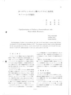
3 Power Down W (3 V) Table 1. Device Information(1). W (5 V) Typical PART NUMBER PACKAGE BODY SIZE (NOM). WSON (6) mm mm DAC081C081. 2 Applications SOT (6) mm mm DAC081C085 VSSOP (8) mm mm Industrial Process Control Portable Instruments (1) For all available packages, see the orderable addendum at the end of the data sheet. Digital Gain and Offset Adjustments Programmable Voltage and Current Sources Test Equipment Figure 1. Block Diagram VA* VREF* GND. DAC081C081 / DAC081C085. Power -ON. RESET. REF. DAC. 8 BIT DAC BUFFER VOUT. REGISTER. 8. 8. 100k 2 Power -DOWN. I C CONTROL. INTERFACE LOGIC. * NOTE: ADR1 and VREF are for the DAC081C085 only. The DAC081C085 uses an external reference (VREF), whereas, the DAC081C081 uses the supply (VA) as the reference. ADR1* ADR0 SCL SDA. 1. An IMPORTANT NOTICE at the end of this data sheet addresses availability, warranty, changes, use in safety-critical applications, intellectual property matters and other important disclaimers.
4 PRODUCTION DATA. DAC081C081, DAC081C085. SNAS449F FEBRUARY 2008 REVISED MAY 2017 Table of Contents 1 Features .. 1 18. 2 Applications .. 1 Registers .. 22. 3 Description .. 1 9 Application and Implementation .. 23. 4 Revision 2 Application 23. Typical Application .. 25. 5 Description (continued).. 3. 6 Pin Configuration and Functions .. 4 10 Power Supply Recommendations .. 26. Using References as Power Supplies .. 26. 7 5. Absolute Maximum Ratings .. 5 11 29. Layout Guidelines .. 29. ESD 5. Layout Example .. 29. Recommended Operating Conditions .. 6. Thermal Information .. 6 12 Device and Documentation Support .. 30. Electrical 7 Device Support .. 30. AC and Timing Characteristics .. 10 Related Links .. 31. Typical Characteristics .. 13 Community 31. Trademarks .. 31. 8 Detailed Description .. 16. Electrostatic Discharge Caution .. 31. Overview.
5 16. Glossary .. 31. Functional Block Diagram .. 16. Feature 16 13 Mechanical, Packaging, and Orderable Device Functional 18. Information .. 31. 4 Revision History NOTE: Page numbers for previous revisions may differ from page numbers in the current version. Changes from Revision E (January 2016) to Revision F Page Added column to Table 1.. 21. Changes from Revision D (March 2013) to Revision E Page Added ESD Ratings table, Feature Description section, Device Functional Modes, Application and Implementation section, Power Supply Recommendations section, Layout section, Device and Documentation Support section, and Mechanical, Packaging, and Orderable Information section.. 1. Added addresses that the DAC responds to on the I2C bus.. 21. Changes from Revision C (March 2013) to Revision D Page Changed layout of National Data Sheet to TI format.
6 29. 2 Submit Documentation Feedback Copyright 2008 2017, Texas Instruments Incorporated Product Folder Links: DAC081C081 DAC081C085. DAC081C081, DAC081C085. SNAS449F FEBRUARY 2008 REVISED MAY 2017. 5 Description (continued). The DAC081C081 and DAC081C085 each have a 16-bit register that controls the mode of operation, the Power - down condition, and the output voltage. A Power -on reset circuit ensures that the DAC output powers up to zero volts. A Power -down feature reduces Power consumption to less than a microWatt. Their low Power consumption and small packages make these DACs an excellent choice for use in battery-operated equipment. Each DAC. operates over the extended industrial temperature range of 40 C to +125 C. The DAC081C081 and DAC081C085 are each part of a family of pin-compatible DACs that also provide 12- and 10-bit resolution.
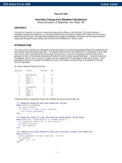
7 For 12-bit DACs see the DAC121C081 and DAC121C085. For 10-bit DACs see the DAC101C081 and DAC101C085. Copyright 2008 2017, Texas Instruments Incorporated Submit Documentation Feedback 3. Product Folder Links: DAC081C081 DAC081C085. DAC081C081, DAC081C085. SNAS449F FEBRUARY 2008 REVISED MAY 2017 6 Pin Configuration and Functions NGF Package 6-Pin WSON DDC Package Top View 6-Pin SOT. Top View ADR0 1 6 VOUT. VOUT 1 6 ADR0. SCL 2 WSON 5 VA. VA 2 SOT 5 SCL. SDA 3 4 GND. GND 3 4 SDA. DAC081C081. DAC081C081. DGK Package 8-Pin VSSOP. Top View ADR0 1 8 VOUT. ADR1 2 7 VREF. VSSOP. SCL 3 6 VA. SDA 4 5 GND. DAC081C085. Table 2. Pin Functions PIN EQUIVALENT. TYPE DESCRIPTION. NAME WSON SOT VSSOP CIRCUIT. Tri-state Address Selection Input. Sets the two Least Digital Input, ADR0 1 6 1 V+. Significant Bits (A1 and A0) of the 7-bit slave address. three levels PIN.
8 D1. (see Table 3). Snap Back Digital Input, Tri-state Address Selection Input. Sets Bits A6 and A3. ADR1 2. three levels GND of the 7-bit slave address. (see Table 3). GND 4 3 5 Ground Ground for all on-chip circuitry. Exposed die attach pad can be connected to ground (WSON or left floating. Soldering the pad to the PCB offers PAD Ground only) optimal thermal performance and enhances package self-alignment during reflow. Serial Clock Input. SCL is used together with SDA to SCL 2 5 3 Digital Input control the transfer of data in and out of the device. PIN. D1 Serial Data bidirectional connection. Data is clocked Snap Back into or out of the internal 16-bit register relative to the Digital SDA 3 4 4 clock edges of SCL. This is an open drain data line Input/Output GND that must be pulled to the supply (VA) by an external pullup resistor. Power supply input.
9 For the SOT and WSON versions, VA 5 2 6 Supply this supply is used as the reference. Must be decoupled to GND. Analog VOUT 6 1 8 Analog Output Voltage Output Unbufferred reference voltage. For the VSSOP-8, this VREF 7 Supply supply is used as the reference. VREF must be free of noise and decoupled to GND. 4 Submit Documentation Feedback Copyright 2008 2017, Texas Instruments Incorporated Product Folder Links: DAC081C081 DAC081C085. DAC081C081, DAC081C085. SNAS449F FEBRUARY 2008 REVISED MAY 2017. 7 Specifications Absolute Maximum Ratings (1) (2) (3). See MIN MAX UNIT. Supply voltage, VA V. Voltage on any Input Pin V. Input current at any pin (4) 10 mA. Package input current (4) 20 mA. (5). Power consumption at TA = 25 C See Junction temperature 150 C. Storage temperature, Tstg 65 150 C. (1) Stresses beyond those listed under Absolute Maximum Ratings may cause permanent damage to the device.
10 These are stress ratings only, which do not imply functional operation of the device at these or any other conditions beyond those indicated under Recommended Operating Conditions. Exposure to absolute-maximum-rated conditions for extended periods may affect device reliability. (2) All voltages are measured with respect to GND = 0 V, unless otherwise specified. (3) If Military/Aerospace specified devices are required, please contact the TI Sales Office/Distributors for availability and specifications. (4) When the input voltage at any pin exceeds V or is less than GND, the current at that pin should be limited to 10 mA. The 20-mA. maximum package input current rating limits the number of pins that can safely exceed the Power supplies with an input current of 10. mA to two. (5) The absolute maximum junction temperature (TJmax) for this device is 150 C.