Transcription of DATA SHEET - Yageo
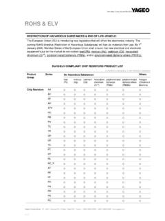
1 data SHEET THICK FILM CHIP RESISTORS AUTOMOTIVE GRADE AC series 5%, 1%, Sizes 0201/0402/0603/0805/1206/ 1210/1218/2010/2512 RoHS compliant & Halogen free Product specification June 20, 2017 Chip Resistor Surface Mount Jun. 20, 2017 Product specification 2 12 SERIES AC 0201 to 2512 ORDERING INFORMATION - GLOBAL PART NUMBER Part number is identified by the series name, size, tolerance, packaging type, temperature coefficient, taping reel and resistance value. SCOPE This specification describes AC0201 to AC2512 chip resistors with lead-free terminations made by thick film process.
2 APPLICATIONS All general purpose applications Car electronics, industrial application FEATURES AEC-Q200 qualified Moisture sensitivity level: MSL 1 AC series soldering is compliant with J-STD-020D Halogen free epoxy RoHS compliant - Products with lead-free terminations meet RoHS requirements - Pb-glass contained in electrodes, resistor element and glass are exempted by RoHS Reduce environmentally hazardous waste High component and equipment reliability The resistors are 100% performed by automatic optical inspection prior to taping. ORDERING EXAMPLE The ordering code for an AC0402 chip resistor, value 100 K with 1% tolerance, supplied in 7-inch tape reel is: AC0402FR-07100KL.
3 NOTE 1. All our R-Chip products are RoHS compliant and Halogen free. "LFP" of the internal 2D reel label states "Lead-Free Process". 2. On customized label, "LFP" or specific symbol can be printed. 3. AC series with tolerance is also available. For further information, please contact sales. Resistance rule of global part number Resistance coding rule Example XRXX (1 to ) 1R = 1 1R5 = 9R76 = XXRX (10 to ) 10R = 10 97R6 = XXXR (100 to 976 ) 100R = 100 976R = 976 XKXX (1 to K ) 1K = 1,000 9K76 = 9760 XMXX (1 to M ) 1M = 1,000,000 9M76= 9,760,000 XXMX (10 M ) 10M = 10,000,000 GLOBAL PART NUMBER AC XXXX X X X XX XXXX L (1) (2) (3) (4) (5) (6) (7) (1) SIZE 0201/ 0402 / 0603 / 0805 / 1206 / 1210 / 1218 / 2010 / 2512 (2) TOLERANCE D = F = 1% J = 5% (for Jumper ordering, use code of J) (3)
4 PACKAGING TYPE R = Paper taping reel K = Embossed taping reel (4) TEMPERATURE COEFFICIENT OF RESISTANCE = Base on spec (5) TAPING REEL 07 = 7 inch dia. Reel 10 = 10 inch dia. Reel 13 = 13 inch dia. Reel 7W = 7 inch dia. Reel & 2 x standard power (6) RESISTANCE VALUE 1 to 22 M There are 2~4 digits indicated the resistance value. Letter R/K/M is decimal point, no need to mention the last zero after R/K/M, , not 1K20. Detailed coding rules of resistance are shown in the table of Resistance rule of global part number . (7) DEFAULT CODE Letter L is the system default code for ordering only. (Note) Chip Resistor Surface Mount Jun.
5 20, 2017 Product specification 3 12 SERIES AC 0201 to 2512 MARKING AC0201 / AC0402 No marking AC0603 / AC0805 / AC1206 / AC1210 / AC2010 / AC2512 E-24 series: 3 digits, 5% First two digits for significant figure and 3rd digit for number of zeros AC0603 E-24 series: 3 digits, 1% & One short bar under marking letter E-96 series: 3 digits, 1% & First two digits for E-96 marking rule and 3rd letter for number of zeros AC0805 / AC1206 / AC1210 / AC2010 / AC2512 Both E-24 and E-96 series: 4 digits, 1% & First three digits for significant figure and 4th digit for number of zeros AC1218 E-24 series: 3 digits, 5% First two digits for significant figure and 3rd digit for number of zeros Both E-24 and E-96 series: 4 digits, 1% & First three digits for significant figure and 4th digit for number of zeros NOTE For further marking information, please refer to data SHEET Chip resistors marking.
6 Marking of AC series is the same as RC series. Fig. 5 Value = 10 K Fig. 1 Fig. 6 Value = 10 K Fig. 2 Value=10 K 03 Fig. 3 Value = 24 0 Fig. 4 Value = K Fig. 7 Value = 10 K 00 Chip Resistor Surface Mount Jun. 20, 2017 Product specification 4 12 SERIES AC 0201 to 2512 overcoatprotectiveglassresistivelayer(Ju mperchipisaconductor)innerelectrodetermi nation(Ni/mattetin)ceramicsubstratemarki nglayerinnerelectrodeYNSC088 Fig. 8_1 Chip resistor outlines OOUUTTLLIINNEESS CONSTRUCTION The resistors are constructed on top of an automotive grade ceramic body.
7 Internal metal electrodes are added at each end and connected by a resistive glaze. The resistive glaze is covered by a protective glass. The composition of the glaze is adjusted to give the approximately required resistance value and laser trimming of this resistive glaze achieves the value within tolerance. The whole element is covered by a protective overcoat. Size 0603 and bigger is marked with the resistance value on top. Finally, the two external terminations (Ni / matte tin) are added, as shown in overcoatprotectiveglassresistivelayer(Ju mperchipisaconductor)innerelectrodetermi nation(Ni/matte tin)ceramicsubstratemarkinglayerinnerele ctrodeYNSC088_1 Fig.
8 8_2 AC2010/ 2512 double power chip resistor outlines For dimension, please refer to Table 1 0603/0805/1206/1210/ 2010/2512 AC1218 Side view for all type AC0201/0402 Fig. 9 Chip resistor dimensions TYPE L (mm) W (mm) H (mm) I1 (mm) I2 (mm) AC0201 AC0402 AC0603 AC0805 AC1206 AC1210 AC1218 AC2010 AC2512 Table 1 For outlines, please refer to Fig. 9 DIMENSIONS Chip Resistor Surface Mount Jun.
9 20, 2017 Product specification 5 12 SERIES AC 0201 to 2512 TYPE POWER CHARACTERISTICS Operating Temperature Range Max. Working Voltage Max. Overload Voltage Dielectric Withstanding Voltage Resistance Range Temperature Coefficient Jumper Criteria AC0201 1/20 W 55 C to 155 C 25V 50V 50V 5% (E24) 1 R 10M 1% (E24/E96) 1 R 10M (E24/E96) 10 R 1M Jumper<50m 1 R 10 -100/+350ppm C 10 < R 10M 200ppm C Rated Current Maximum Current AC0402 1/16 W 55 C to 155 C 50V 100V 100V 5% (E24) 1 R 22M , 1% (E24/E96) 1 R 10M Jumper<50m 1 R 10 200ppm C 10 < R 10M 100ppm C 10M < R 22M 200ppm C Rated Current 1A Maximum Current 2A 1/8W 55 C to 155 C 50V 100V 100V 5% (E24) 1 R 10M , 1% (E24/E96)
10 1 R 10M 1 R 10 200 ppm C 10 < R 10M 100 ppm C AC0603 1/10 W 55 C to 155 C 75V 150V 150V 5% (E24) 1 R 22M , 1% (E24/E96) 1 R 10M Jumper<50m 1 R 10 200ppm C 10 < R 10M 100ppm C 10M < R 22M 200ppm C Rated Current 1A Maximum Current 2A 1/5 W 55 C to 155 C 75V 150V 150V 5% (E24) 1 R 10M , 1% (E24/E96) 1 R 10M 1 R 10 200 ppm C 10 < R 10M 100 ppm C ELECTRICAL CHARACTERISTICS Table 2 Chip Resistor Surface Mount Jun. 20, 2017 Product specification 6 12 SERIES AC 0201 to 2512 TYPE POWER CHARACTERISTICS Operating Temperature Range Max.