Transcription of 150V VIN and VOUT Synchronous 4-Switch Buck-Boost ...
1 LTC37791 Rev AFor more information FeedbackTYPICAL APPLICATION FEATURESDESCRIPTION150V VIN and VOUT Synchronous 4-Switch Buck-Boost ControllerThe LT C 3779 is a high performance Buck-Boost switching regulator controller that operates from input voltages above, below or equal to the output voltage. The constant frequency current mode architecture allows a phase-lockable frequency of up to 600kHz, while an input/output constant-current loop provides support for battery charging. With a wide to 150V input and output range and seamless transfers between operating regions, the LTC3779 is ideal for automotive, telecom and battery-powered systems. The LTC3779 features a precision reference and power good output indicator. The MODE pin can select between pulse-skipping mode or forced continuous mode of operation. Pulse-skipping mode offers high efficiency at light load while forced continuous mode operates at a constant frequency for noise sensitive applications.
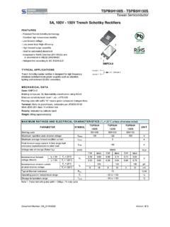
2 The PLLIN pin allows the IC to be synchronized to an external clock. The SS pin ramps the output voltage during start-up. Current foldback limits MOSFET heat dissipation during short-circuit n4-Switch Current Mode Single Inductor Architecture Allows VIN Above, Below or Equal to VOUT nWide VIN Range: to 150V nWide Output Voltage Range: VOUT 150V nSynchronous Rectification: Up to 99% Efficiency n 1% Voltage Reference nInput or Output Average Current Limit nOnboard LDO or External NMOS LDO for DRVCC n36V EXTVCC LDO Powers Drivers nProgrammable 6V to 10V DRVCC Optimizes Efficiency nNo Top FET Refresh Noise in Boost or Buck Mode nVOUT Disconnected from VIN During Shutdown nPhase-Lockable Fixed Frequency (50kHz to 600kHz) nNo Reverse Current During Start-Up nPower Good Output Voltage Monitor n150V Rated RUN Pin with Accurate Turn-On Threshold nProgrammable Input Overvoltage Lockout nThermally Enhanced FE38 TSSOP Package Modified for High Voltage Operation nIndustrial, Automotive, Medical, Military, AvionicsEfficiency and Power Loss vs Input VoltageVOUT = 48 VIOUT = 10 AEFFICIENCYPOWER LOSSVIN VOLTAGE (V)0122436486072849610812090929496981000 612182430 EFFICIENCY (%)POWER LOSS (W)
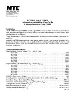
3 3779 F4m 4m 30 F475k15 100 F10k5 F5 F56 FVIN20V TO 120V20 FVOUT48V10A100 100 All registered trademarks and trademarks are the property of their respective AFor more information CONFIGURATIONABSOLUTE MAXIMUM RATINGSI nput Supply Voltage (VIN) ..150V to Driver Voltage BOOST1, BOOST2 ..161V to Voltage SW1, SW2 ..150V to 5 VRUN ..150V to , IAVGSNSN ..150V to 10 VVINSNS, VOUTSNS ..150V to Voltage .. 36V to Voltage ..(Note 9)DRVCC Voltage ..11V to , BOOST2-SW2 ..11V to , TG2-SW2, BG1, BG2 ..(Note 8)V5 to , PLLIN, SS, PGOOD ..V5 to , FREQ, DRVSET ..V5 to , SENSEN, VINOV ..V5 to Voltage .. to Junction Temperature Range (Notes 2, 3) .. 40 C to 150 CStorage Temperature Range .. 65 C to 150 CEXTVCC/ DRVCC Peak Current ..100mA (Note 1)12345678910111213141516171819 TOP VIEWFE PACKAGEVARIATION: FE38(31)38-LEAD PLASTIC TSSOP383736343230282624222120BG1 VINOVDRVSETSGNDEXTVCCNDRVDRVCCV5 SSVFBSENSEPSENSENITHSGNDMODEPLLINFREQPGO ODBG2SW1TG1 BOOST1 VINVINSNSVOUTSNSIAVGSNSNIAVGSNSPRUNBOOST 2TG2SW239 PGND TJMAX = 150 C, JA = 28 C/W EXPOSED PAD (PIN 39) IS PGND, MUST BE SOLDERED TO PCBFOR RATED ELECTRICAL AND THERMAL CHARACTERISTICSORDER INFORMATIONLEAD FREE FINISHTAPE AND REELPART MARKINGPACKAGE DESCRIPTIONTEMPERATURE RANGELTC3779 EFE#PBFLTC3779 EFE#TRPBFLTC3779FE38-Lead Plastic TSSOP 40 C to 125 CLTC3779 IFE#PBFLTC3779 IFE#TRPBFLTC3779FE38-Lead Plastic TSSOP 40 C to 125 CLTC3779 HFE#PBFLTC3779 HFE#TRPBFLTC3779FE38-Lead Plastic TSSOP 40 C to 150 CConsult ADI Marketing for parts specified with wider operating temperature more information on lead free part marking, go to: For more information on tape and reel specifications, go to.
4 Some packages are available in 500 unit reels through designated sales channels with #TRMPBF #orderinfoLTC37793 Rev AFor more information CHARACTERISTICS The l denotes the specifications which apply over the specified operating junction temperature range, otherwise specifications are at TA = 25 C (Note 2), VIN = 15V, VRUN = 5V, VEXTVCC = 0V, VDRVSET = 0V, VVINOV = 0V unless otherwise Supply Operating Voltage Range(Note 4) Supply Operating Voltage Feedback Voltage(Note 5); ITH Voltage = Current(Note 5) 15-50nAReference Voltage Line Regulation(Note 5); VIN = 7V to Voltage Load Regulation(Note 5); Measured in Servo Loop; ITH Voltage = to Amplifier gm(Note 5); ITH = ; Sink/Source 5 DC Supply Current(Note 6) = 0V4075 AUndervoltage LockoutV5 Ramping Ramping Pin ON ThresholdVRUN Pin Hysteresis100mVRUN Pin Source CurrentVRUN < ARUN Pin Hysteresis CurrentVRUN > AVIN Overvoltage Lockout Threshold (Rising)VVINOV Overvoltage Hysteresis50mVSENSE Pins CurrentVSENSEP = VSENSEN = 0 2 AIAVGSNSP IAVGSNSNIAVGSNS Pins CurrentVIAVGSNSP = VIAVGSNSN = 10V15 ASoft-Start Charge CurrentVSS = 0V456 AVSENSE(MAX)Maximum Current Sense Threshold (Buck Region Valley Current Mode)VFB = 1Vl7090110mVMaximum Current Sense Threshold (Boost Region Peak Current Mode)VFB = 1Vl120140160mVMaximum Input / Output Average Current Sense Threshold VIAVGSNSP = VIAVGSNSN = 10V, VFB = (MAX, BOOST)Maximum Duty Factor% Switch C On90%DCON(MIN, BOOST)Minimum Duty Factor for Main Switch in Boost Operation% Switch C On9%DCON(MIN, BUCK)
5 Minimum Duty Factor for Main Switch in Buck Operation% Switch B On9%Gate DriverTG Pull-Up On Resistance TG Pull-Down On ResistanceVDRVCC = BG Pull-Up On Resistance BG Pull-Down On ResistanceVDRVCC = 3 TG Transition Time: Rise Time Fall TimeVDRVCC = 9V (Note 7) CLOAD = 3300pF 60 nsBG Transition Time: Rise Time Fall TimeVDRVCC = 9V (Note 7) CLOAD = 3300pF 60 nsLTC37794 Rev AFor more information CHARACTERISTICS The l denotes the specifications which apply over the specified operating junction temperature range, otherwise specifications are at TA = 25 C (Note 2), VIN = 15V, VRUN = 5V, VEXTVCC = 0V, VDRVSET = 0V, VVINOV = 0V unless otherwise Gate Off to Bottom Gate On Delay Synchronous Switch-On Delay TimeCLOAD = 3300pF Each Driver, VDRVSET = V560nsBottom Gate Off to Top Gate On Delay Top Switch-On Delay TimeCLOAD = 3300pF Each Driver, VDRVSET = V560nsDRVCC LDO RegulatorVDRVCCDRVCC Regulation Voltage from NDRV RegulatorNDRV Driving External NFET, VEXTVCC = 0V 7V < VIN < 150V, VDRVSET = 0V 8V < VIN < 150V, VDRVSET = 1/4 VV5 9V < VIN < 150V, VDRVSET = Float 10V < VIN < 150V, VDRVSET = 3/4 VV5 11V < VIN < 150V, VDRVSET = VV5 10 V V V V VDRVCC Regulation Voltage from Internal VIN LDOVNDRV = VDRVCC, VEXTVCC = 0V 7V < VIN < 150V, VDRVSET = 0V 8V < VIN < 150V, VDRVSET = 1/4 VV5 9V < VIN < 150V, VDRVSET = Float 10V < VIN < 150V, VDRVSET = 3/4 VV5 11V < VIN < 150V.
6 VDRVSET = VV5 V V V V VDRVCC Load Regulation from VIN LDOICC = 0mA to 50mA, VEXTVCC = Regulation Voltage from Internal EXTVCC LDO7V < VEXTVCC < 30V, VDRVSET = 0V 8V < VEXTVCC < 30V, VDRVSET = 1/4 VV5 9V < VEXTVCC < 30V, VDRVSET = Float 10V < VEXTVCC < 30V, VDRVSET = 3/4 VV5 11V < VEXTVCC < 30V, VDRVSET = V V V VDRVCC Load Regulation from Internal EXTVCC LDOICC = 0mA to 50mA, VEXTVCC = 12V VDRVSET = LDO Switchover Voltage EXTVCC Ramping Positive DRVCC Hysteresis% of DRVCC Regulation Voltage10%V5 Linear RegulatorV5 Regulation Voltage6V < VDRVCC < Load RegulationIV5 = 0mA to 20mA, VDRVCC = and Phase-Locked LoopNominal FrequencyRFREQ = 225250275kHzLow Fixed FrequencyRFREQ 20k 304050kHzHigh Fixed FrequencyRFREQ = 135k 450500550kHzPLLIN Input ThresholdVPLLIN Rising VPLLIN Falling2 VPLLIN Input Resistance200k Synchronizable Oscillator FrequencyPLLIN = External Clockl50600kHzIFREQF requency Setting Currentl182022 APGOOD OutputPGOOD Voltage LowIPGOOD = 2mA Leakage CurrentVPGOOD = 1 APGOOD Trip LevelVFB with Respect to Set Regulated VoltageVFB Ramping Negative 10%VFB Ramping Positive10%PGOOD delayVPGOOD High to Low125 sLTC37795 Rev AFor more information CHARACTERISTICSNote 1: Stresses beyond those listed under Absolute Maximum Ratings may cause permanent damage to the device.
7 Exposure to any Absolute Maximum Rating condition for extended periods may affect device reliability and 2: The LTC3779 is tested under pulsed load conditions such that TJ TA. The LTC3779E is guaranteed to meet performance specifications from 0 C to 85 C junction temperature. Specifications over the 40 C to 125 C operating junction temperature range are assured by design, characterization and correlation with statistical process controls. The LTC3779I is guaranteed over the full 40 C to 125 C operating junction temperature range. The LTC3779H is guaranteed over the full 40 C to 150 C operating junction temperature range. High junction temperature degrades operating lifetimes; operating lifetime is derated for junction temperatures greater than 125 C. Note that the maximum ambient temperature consistent with these specifications is determined by specific operating conditions in conjunction with board layout, the rated package thermal impedance and other environmental factors.
8 The junction temperature TJ is calculated from the ambient temperature TA and power dissipation PD according to the formula: TJ = TA + (PD JA), where JA = 28 C/W for the TSSOP package. Note 3: This IC includes over temperature protection that is intended to protect the device during momentary overload conditions. The maximum rated junction temperature will be exceeded when this protection is active. Continuous operation above the specified absolute maximum operating junction temperature may impair device reliability or permanently damage the device. Note 4: When biased from an auxiliary supply through the EXTVCC pin, the LTC3779 can operate from a VIN voltage lower than Otherwise the minimum VIN operational voltage is after 5: The LTC3779 is tested in a feedback loop that servos VITH to a specified voltage and measures the resultant 6: Dynamic supply current is higher due to the gate charge being delivered at the switching frequency.
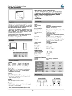
9 See Applications 7: Rise and fall times are measured using 10% and 90% levels. Delay times are measured using 50% 8: Do not apply a voltage or current source to these pins. They must be connected to capacitive loads only, otherwise permanent damage may occur. These pins are rated for an absolute maximum voltage of to 11V. Note 9: Do not apply a voltage or current source to the NDRV pin, other than tying NDRV to DRVCC when not used. If used it must be connected to capacitive loads only (see DRVCC Regulator in the Applications Information section), otherwise permanent damage may AFor more information PERFORMANCE CHARACTERISTICSE fficiency and Power Loss vs Load Current and Input Voltage Continuous ModeEfficiency and Power Loss vs Input VoltageLoad Step Boost Region Continuous ModeLoad Step Boost Region Pulse-Skipping ModeLoad Step Buck-Boost Region Continuous ModeLoad Step Buck-Boost Region Pulse-Skipping ModeLoad Step Buck Region Continuous ModeLoad Step Buck Region Pulse-Skipping ModeVOUT = 12 VIOUT = 5 AEFFICIENCYFIGURE 17 CIRCUITPOWER LOSSVIN VOLTAGE (V)5101520253035404550558588919497100024 6810 EFFICIENCY (%)POWER LOSS (W)
10 3779 G02200 s/DIVVIN = 36 VVOUT = 48 VILOAD5A/DIVIL5A/DIVVOUT1V/DIVAC-COUPLED 3779 G03200 s/DIV3779 G04 VIN = 36 VVOUT = 48 VILOAD5A/DIVIL5A/DIVVOUT1V/DIVAC-COUPLED 200 s/DIV3779 G05 VIN = 48 VVOUT = 48 VILOAD5A/DIVIL5A/DIVVOUT1V/DIVAC-COUPLED 200 s/DIV3779 G06 VIN = 48 VVOUT = 48 VILOAD5A/DIVIL5A/DIVVOUT1V/DIVAC-COUPLED 200 s/DIV3779 G07 VIN = 120 VVOUT = 48 VILOAD5A/DIVIL5A/DIVVOUT1V/DIVAC-COUPLED 200 s/DIV3779 G08 VIN = 120 VVOUT = 48 VILOAD5A/DIVIL5A/DIVVOUT1V/DIVAC-COUPLED VOUT = 48 VfSW = 250kHzEFFICIENCYPOWER LOSSVIN = 72 VVIN = 48 VVIN = 24 VLOAD CURRENT (A)FIGURE 18 (%)POWER LOSS (W)3779 G01 LTC37797 Rev AFor more information PERFORMANCE CHARACTERISTICSF orced Continuous Mode Boost RegionPulse-Skipping Mode Boost RegionForced Continuous Mode Buck-Boost RegionPulse-Skipping Mode Buck-Boost RegionForced Continuous Mode Buck RegionPulse-Skipping Mode Buck RegionStart-Up from RUN Forced Continuous Mode Pre-Biased Output5 s/DIV3779 G09IL5A/DIVVOUT200mV/DIVAC-COUPLEDSW2100 V/DIVSW1100V/DIVVIN = 24 VVOUT = 48 VILOAD = 0A5 s/DIV3779 G10IL5A/DIVVOUT200mV/DIVAC-COUPLEDSW2100 V/DIVSW1100V/DIVVIN = 24 VVOUT = 48 VILOAD = 0A5 s/DIV3779 G11IL1A/DIVVOUT200mV/DIVAC-COUPLEDSW2100 V/DIVSW1100V/DIVVIN = 48 VVOUT = 48 VILOAD = 0A5 s/DIV3779 G12 VIN = 48 VVOUT = 48 VILOAD = 0 AIL1A/DIVVOUT200mV/DIVAC-COUPLEDSW2100V/ DIVSW1100V/DIV5 s/DIV3779 G13IL5A/DIVVOUT200mV/DIVAC-COUPLEDSW2100 V/DIVSW1100V/DIVVIN = 120 VVOUT = 48 VILOAD = 0A5 s/DIV3779 G14 VIN = 120 VVOUT = 48 VILOAD = 0 AIL5A/DIVVOUT200mV/DIVAC-COUPLEDSW2100V/ DIVSW1100