Transcription of DC/DC Converter Controller Using a PICmicro Controller
1 2000 Microchip Technology 1AN216 INTRODUCTIONIn many applications, a DC/DC Converter is used toproduce a regulated voltage or current, derived from anunregulated power supply, or from a battery. Examplesof these applications include battery chargers, elec-tronic air purifiers, emergency exit signs, and distrib-uted power some of those applications, a dedicated SwitchedMode Power Supply (SMPS) Controller IC is used inconjunction with a microcontroller. In other applica-tions, however, a dedicated SMPS Controller IC may beoverkill.
2 An alternative approach is to generate a lowcost SMPS function in a smart microcontroller, such asthe PIC16C620A. This Application Note shows amethod of Using the microcontroller to perform simpleSMPS control circuits were built for evaluation. One circuit pro-vides a Constant Voltage output, the other a ConstantCurrent CONVERTERT here are several popular DC/DC Converter topolo-gies, such as the Boost and Fly-back Converter topolo-gies. The DC/DC Converter used in this example is aBuck (or step down) Converter , which is also a populartopology.
3 In Figure 3, the Buck Converter consists oftransistor Q1, diode D1, inductor L1, and capacitor Q2 is used as a level translator for thePICmicro device PORTB output to turn Q1 on or off. Application Note AN701 explains how a Buck Con-verter works. It also provides a general guideline oncomponent any type of DC/DC Converter circuit, the powerdevice selections are very important. The key parame-ters to look for in the transistor Q1 are the switchingtime and current rating. These two parameters greatlyaffect the maximum switching frequency of the con-verter, and also how much current the Converter can bedesigned for.
4 The diode D1 should either be a Schottky,or ultra fast diode, in order to minimize switching lossesin the Converter . The type of capacitor C1 is also veryimportant to minimize the ripple on the Converter out-put. An electrolytic capacitor with a low ESR (Equiva-lent Series Resistance) is desirable for capacitor some cases, the output ripple of the Converter maystill be higher than desired, even with the proper induc-tor and capacitor selections. In this case, an additionalinductor and capacitor may be used as a low pass filterat the Converter DC/DC Converter is normally chosen because of itshigh efficiency in converting the input power to outputpower.
5 Unlike a linear regulator, the efficiency measureof a DC/DC Converter generally increases as its loadincreases. A properly designed DC/DC Converter canyield an efficiency measure of greater than 90% at fullload. The efficiency of a DC/DC Converter is expressedas the ratio of output power and input power. The fol-lowing equations can be used to determine = POUT/PIN * 100%orEfficiency = VOUT * IOUT/(VIN * IIN) * 100%The selection of the DC/DC Converter components, inmany cases, is a trade-off between cost, performance,and size. In this Application Note, the component selec-tions were made to simply provide a DC/DC Converterthat can be used to demonstrate the PIC16C620 Acapability to perform SMPS Controller function.
6 TheDC/DC Converter discussed here is not optimized forany particular :Hartono DarmawaskitaMicrochip Technology Converter Controller Using aPICmicro MicrocontrollerAN216DS00216A-page 2 Preliminary 2000 Microchip Technology Controller FUNCTIONThe DC/DC Converter circuit is merely a power proces-sor. It transforms the available input voltage and cur-rent into the output voltage and current, based on thecommand of the SMPS Controller . The SMPS controllerlooks at the Converter output, compares the output to aset point, performs a control algorithm and finally,applies the algorithm output to a modulator.
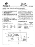
7 The modu-lator output is then used to drive the DC/DC 1 shows a simplified block diagram of a com-plete DC/DC Converter system. In this ApplicationNote, the PIC16C620A is used to implement the SMPS Controller function, which includes the following func-tions: set point generation, error amplifier, control algo-rithm, and the modulator. These functions are showninside the dashed box in Figure 1: DC/DC Converter SYSTEMSetPoint+-ErrorControlAlgorithmCon trolSignalModulatorPIC16C620A(SMPS Controller Function)PSMS ignalDC/DCConverterInput VoltageLoadOutputFeedbackCircuit 2000 Microchip Technology 3AN216 MODULATOR - PULSE SKIPPING MODULATION (PSM)One of the simplest modulation techniques used forcontrolling a DC/DC Converter is Pulse Skipping Mod-ulation (PSM), which is also known as Pulsed Fre-quency Modulation.
8 In a PSM system, the modulatorgenerates a train of pulses to turn the Converter powerswitch on and off. The pulses have a fixed pulse width,as well as period. As long as the Converter output isbelow the desired target, the PSM pulses continue torun the Converter switch. Once the Converter outputreaches or exceeds the target, the next PSM pulse isskipped. This operation will result in decreasing pulsedensity as the Converter output reaches its target, or asthe output loading decreases. When the Converter out-put falls below the target, or as the output loadingincreases, the PSM pulse density will theoretical limit of the maximum output voltage isdetermined by the input voltage to the DC/DC Con-verter and the maximum duty cycle of the PSM signal,which is the duty cycle of the PSM signal when it is con-tinuously running (not skipping pulses).
9 This relation-ship can be expressed as follows:VOUTMAX = VIN * dmaxThis formula does not take into account the conductionand switching losses of the Converter components. Thediscussion of non-ideal DC/DC Converter is beyond thescope of this Application Note. However, many papersand text books are available on this this application, the PIC16C620A microcontrollerperforms the modulator function in firmware. This firm-ware modulator generates the PSM pulses on the RB7pin (PORTB, bit 7), to drive transistor Q2 of the DC/DCConverter. When the DC/DC Converter output is belowthe desired value, the firmware continuously sends outPSM pulses to increase the Converter output.
10 Once theDC/DC Converter output exceeds the target, the con-troller will skip the PSM pulses until the output voltage,or current, falls below the threshold and the controlcycle of the microcontroller is used to generate a timebase for the firmware modulator. Timer0 is enabled andthe TMR0 register is loaded with a reload value. WhenTimer0 overflows, an interrupt occurs. In the interruptroutine, TMR0 is again loaded with the reload reload value determines the time base of the PSMsignal. In this application, the TMR0 reload value ischosen to produce a time base of 50 microsecondswhen the microcontroller runs from a 16 MHz crystal frequencies may be used; however, the16 MHz was selected to give plenty of instructioncycles in between Timer0 interrupts, for the firmwareexecution.