Transcription of DC Motor Angular Position Control using PID Controller ...
1 International Journal of Scientific and Research Publications, Volume 8, Issue 11, November 2018 149 ISSN 2250-3153 DC Motor Angular Position Control using PID Controller with Friction Compensation Myo Maung Maung*, Maung Maung Latt**, Chaw Myat Nwe** * Department of Electronic Engineering, Mandalay Technological University, Republic of the Union of MYANMAR ** Technological University, Taungoo, Republic of the Union of MYANMAR ** Department of Electronic Engineering, Mandalay Technological University, Republic of the Union of MYANMAR DOI: Abstract- This paper finds to get the precision of Angular Position Control for DC geared Motor using PID Controller .
2 The Arduino microcontroller board is mainly used to Control the 12V brushed Namiki DC Motor . L298N dual H-bridge Motor driver is applied to execute the pulse width modulation (PWM) signal and to drive the direction Control . The implementation code is considered to generate the PWM output using PID (proportional, integral and derivative) tuning algorithms. According to the PID tuning method, errors are not only solved but also taken to its minimal value with very low amount of error oscillations. In this work, step input, sine input and potentiometer input are tested to analyze the system performance. The results were clearly seen, the Controller output response curve is very well-matched to approach the desired Position .
3 But, it has a few errors when the orientation of changes angle because they are not fast to reach the desired Position . Therefore, friction compensation according to the velocity effect is considered. After compensating the friction effect, the PID output results were very precise to get the desired angle. This stability performance using PID Controller can be applied for robotic arm Position Control system and other industrial applications. Index Terms- DC-Gear Motor , L298 Motor Driver, PID, PWM Control I. INTRODUCTION owadays,the DC motors are used in various applications such as defense, industries, robotics because of their simplicity, ease of application, reliability and cost effective.
4 Generally in a DC Motor , speed Control can be achieved by varying the terminal voltage but Position Control of the shaft cannot be achieved. The Position Control of a DC Motor is crucial in applications for precision Control system. The purpose of a Motor Position Controller is to take a signal representing the required angle and to drive a Motor at that Position . Microcontrollers can provide easy Control of a DC Motor . A microcontroller-based Position Control system consists of an electronic component and a microcontroller. There are many applications of DC Motor drives that use power electronics to Control the voltage and consequently the speed or Position of the Motor [1].
5 In this paper, 12V Namiki DC Motor with a metal gearbox is used which has an integrated quadrature encoder. The encoder s read value is corresponding to the Motor pulse counts per revolution of gearbox s output shaft. Geared DC motors on the other hand, can provide high torque. The torque generated at the output shaft of a DC Motor can be scaled up or scaled down by using a gear train [2]. Therefore, this system can get the high torque Position and low speed by using geared DC Motor to provide a feedback loop. Bi-directional Motor Control can be done using an L298 H-Bridge module with pulse-width modulation (PWM) from an Arduino microcontroller.
6 The PWM Control signal is calculated by proportional-integral-derivative (PID) tuning algorithms. PID Controller is a generic Control loop feedback mechanism widely used in industrial Control systems. A PID Controller attempts to correct the error between a measured process variable and a desired set point by calculating and then outputting a corrective action that can adjust the process accordingly. So by integrating the PID Controller to the DC Motor were able to correct the error made by the DC Motor and Control the speed or the Position of the Motor to the desired point or speed. This paper obviously sees the real time DC Motor Position Control for the various input value of Position .
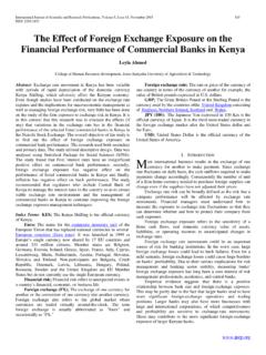
7 Step function, sine function and variable resistor are used as an input signal to test the DC Motor Position . Besides, friction compensation according to the velocity dependence is considered to eliminate the friction effect. By applying the Coulomb s friction force on the driving velocity, the performance of the output results is better to get the desired Position of DC Motor . II. SYSTEM BLOCK DESCRIPTION The block diagram for overall system description is shown in In this block, three main hardware components are implemented for this research. Arduino Uno microcontroller is to Control the Position of DC Motor by controlling the input voltage N International Journal of Scientific and Research Publications, Volume 8, Issue 11, November 2018 150 ISSN 2250-3153 Figure 1: Block Diagram for DC Motor Position Control to the Motor .
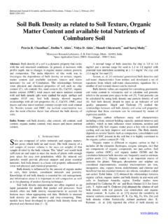
8 PID tuning algorithms is implemented in microcontroller to execute the PWM signal for DC Motor drive. A 12V Namiki DC gear- Motor is a powerful Motor to drive the Position Control system. It comes with the photoelectric encoder output, planetary gear reducer and 80:1 gear ratio, which provide 120 rpm with 12 VDC rated voltage. L298 dual H-Bridge Motor driver which is allows controlling the direction and Position of DC Motor . III . HARDWARE DEVICES A. Arduino Uno Microcontroller Arduino Uno is a microcontroller board based on the ATmega328P shown in Fig. 2. It has 14 digital input/output pins (of which 6 can be used as PWM outputs), 6 analog inputs, a 16 MHz quartz crystal, a USB connection, a power jack, an ICSP header and a reset button.
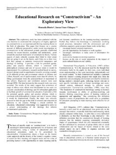
9 It contains everything needed to support the microcontroller; simply connect it to a computer with a USB cable or power it with a AC-to -DC adapter or battery to get started [3]. In this paper, the Arduino microcontroller is very well-suited to drive the PWM signal for DC Motor for the improvement of the output response for the DC Motor Position Control system. Figure 2: Arduino Uno Microcontroller B. L298N Dual H-Bridge Controller The L298N H-bridge IC shows in Fig. 3 that can allow to Control the speed and direction of two DC motors. This module can be used with motors that have a voltage of between 5 and 35V DC with a peak current up to 2A.
10 The module has two screw terminal blocks for the Motor A and B, and another screw terminal block for the Ground pin, the VCC for Motor and a 5V pin which can either be an input or output. Pin assignments for L298N dual H-Bridge Module is shown in table 1. The digital pin assign from HIGH to LOW or LOW to HIGH is used IN1and IN2 on the L298N board to Control the direction. And the Controller output PWM signal is send to ENA or ENB to Control the Position . The forward and reverse speed or Position controlling for the Motor has done by using PWM signal [4]. Then using the analogWrite() function and send the PWM signal to the Enable pin of the L298N board, which actually drives the Motor .