Transcription of Designing Flyback Converters Using Peak-Current-Mode ...
1 Maxim > Design Support > Technical Documents > Application Notes > power -Supply Circuits > APP 5504 Keywords: Flyback , continuous conduction mode, CCM, discontinuous conduction mode, DCM,transformer, optoisolated feedback, error amplifier compensation, pi controller, biasing optocoupler, Flyback converter, peak current mode controller, MAX17596, MAX17595 APPLICATION NOTE 5504 Designing Flyback Converters Using Peak-Current-Mode ControllersBy: Srinivasa Rao MeesalaNov 27, 2012 Abstract: Flyback converter design Using MAX17595/MAX17596 is outlined. Design methodology andcalculations for components value selection are presented. Continuous conduction mode (CCM) anddiscontinuous conduction mode (DCM) are treated individually. IntroductionThis application note describes the methodology of Designing Flyback Converters Using theMAX17595/MAX17596 Peak-Current-Mode controllers.
2 Flyback Converters may be operated indiscontinuous conduction mode (DCM) or continuous conduction mode (CCM). The component choices,stress level in power devices, and controller design vary depending on the operating mode of theconverter. Formulas for calculating component values and ratings are also FlybackPrimary Inductance SelectionIn a DCM Flyback converter, the energy stored in the primary inductance of the Flyback transformer isdelivered entirely to the output. The maximum primary-inductance value for which the converter remainsin DCM at all operating conditions can be calculated as:(Eq. 1)Where DMAX is chosen as for the MAX17595/MAX17596, VD is the voltage drop of the outputrectifier diode on the secondary winding, and FSW is the switching frequency of the power the primary inductance value to be less than Cycle CalculationThe accurate value of the duty cycle (DNEW) for the selected primary inductance (LPRI) can bePage 1 of 23calculated Using the following equation:(Eq.)
3 2)Turns Ratio Calculation (NS/NP)Transformer turns ratio (K = NS/NP) can be calculated as:(Eq. 3)Peak/RMS Current CalculationPrimary and secondary RMS currents and primary peak current calculations are needed to design thetransformer in switched- mode power supplies. Also, primary peak current is used in setting the currentlimit. Use the following equations to calculate the primary and secondary peak and RMS primary peak current, (Eq. 4)Maximum primary RMS current, (Eq. 5)Maximum secondary peak current, (Eq. 6)Maximum secondary RMS current, (Eq. 7)For the purpose of current limit setting, the peak current may be calculated as follows:ILIM = IPRIPEAK (Eq. 8)Primary Snubber SelectionIdeally, the external MOSFET experiences a drain-source voltage stress equal to the sum of the inputvoltage and reflected voltage across the primary winding during the OFF period of the MOSFET.
4 Inpractice, parasitic inductors and capacitors in the circuit, such as leakage inductance of the flybacktransformer, cause voltage overshoot and ringing in addition to the ideally expected voltage circuits are used to limit the voltage overshoots to safe levels within the voltage rating of theexternal MOSFET. The snubber capacitor can be calculated Using the following equation:(Eq. 9)Page 2 of 23 Where LLK is the leakage inductance that can be obtained from the transformer specifications (usually1% to 2% of the primary inductance).The power that must be dissipated in the snubber resistor is calculated Using the following formula:PSNUB = LLK IPRIPEAK FSW(Eq. 10)The snubber resistor is calculated based on the equation below:(Eq. 11)The voltage rating of the snubber diode is:VDSNUB = VINMAX + ( VOUT/K)(Eq. 12)Output Capacitor SelectionX7R ceramic output capacitors are preferred in industrial applications due to their stability overtemperature.
5 The output capacitor is usually sized to support a step load of 50% of the rated outputcurrent in nonisolated applications so that the output voltage deviation is contained to 3% of the ratedoutput voltage. The output capacitance can be calculated as follows:(Eq. 13)(Eq. 14)The output capacitor RMS current rating can be calculated as follows:(Eq. 15)Where ISTEP is the load step, TRESPONSE is the response time of the controller, VOUT is the allowableoutput voltage deviation, and FC is the target closed-loop crossover frequency. FC is chosen to be 1/10of the switching frequency FSW. For the Flyback converter, the output capacitor supplies the load currentwhen the main switch is on, and therefore the output voltage ripple is a function of load current and dutycycle. Use the following equation to calculate the output capacitor ripple:(Eq.)
6 16)Where IOUT is load current and DNEW is the duty cycle at minimum input 3 of 23 Input Capacitor SelectionThe MAX17595 is optimized to implement offline AC-DC Converters . In such applications, the inputcapacitor must be selected based on either the ripple due to the rectified line voltage, or based onholdup-time requirements. Holdup time can be defined as the time period over which the power supplyshould regulate its output voltage from the instant the AC power fails. The MAX17596 is useful inimplementing low-voltage DC-DC applications where the switching-frequency ripple must be used tocalculate the input capacitor. In both cases, the capacitor must be sized to meet RMS currentrequirements for reliable Selection Based on Switching Ripple (MAX17596)For DC-DC applications, X7R ceramic capacitors are recommended due to their stability over theoperating temperature range.
7 The effective series resistance (ESR) and effective series inductance (ESL)of a ceramic capacitor are relatively low, so the ripple voltage is dominated by the capacitive the Flyback converter, the input capacitor supplies the current when the main switch is on. Use thefollowing equation to calculate the input capacitor for a specified peak-to-peak input switching ripple(VIN_RIP):(Eq. 17)The input capacitor RMS current in low-voltage DC-DC applications can be calculated as follows:(Eq. 18)Capacitor Selection Based on Rectified Line Voltage Ripple (MAX17595)For the Flyback converter, the input capacitor supplies the input current when the diode rectifier is voltage discharge on the input capacitor, due to the input average current, should be within thelimits 25% ripple present on input DC capacitor, the input capacitor can be calculated as follows:(Eq.)
8 19)WherePLOAD = rated output power = typical efficiency at VAC,MIN and ILOADVIN,PK = 2 VAC,MIN = peak voltage at minimum input AC Selection Based on Holdup Time Requirements (MAX17595)For a given output power (PHOLDUP) that needs to be delivered during holdup time (THOLDUP), the DCbus voltage at which the AC supply fails (VINFAIL), and the minimum DC bus voltage at which theconverter can regulate the output voltages (VINMIN), the input capacitor (CIN) is estimated as:Page 4 of 23(Eq. 20)The input capacitor RMS current for AC-DC applications can be calculated as:(Eq. 21)External MOSFET SelectionMOSFET selection criteria include maximum drain voltage, peak/RMS current in the primary, and themaximum allowable power dissipation of the package without exceeding the junction temperature voltage seen by the MOSFET drain is the sum of the input voltage, the reflected secondary voltageon the transformer primary, and the leakage inductance spike.
9 The MOSFET s absolute maximum VDSrating must be higher than the worst-case drain voltage:(Eq. 22)The drain current rating of the external MOSFET is selected to be greater than the worst-case peakcurrent limit Diode SelectionSecondary-diode-selection criteria includes the maximum reverse voltage, average current in thesecondary, reverse recovery time, junction capacitance, and the maximum allowable power dissipation ofthe package. The voltage stress on the diode is the sum of the output voltage and the reflected primaryvoltage. The maximum operating reverse-voltage rating must be higher than the worst-case reversevoltage:VSECDIODE = (K VINMAX + VOUT)(Eq. 23)The current rating of the secondary diode should be selected so that the power loss in the diode (givenas the product of forward-voltage drop and the average diode current) should be low enough to ensurethat the junction temperature is within limits.
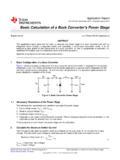
10 Select fast-recovery diodes with a recovery time less than50ns, or Schottky diodes with low junction Amplifier Compensation DesignFor nonisolated designs, output voltage feedback and the loop compensation network are connected asshown in Figure 5 of 23 Figure 1. Loop compensation arrangement for nonisolated loop compensation values are calculated as:(Eq. 24)Where:(Eq. 25)FSW is the switching FlybackTransformer Turns Ratio Calculation (K = NS/NP)The transformer turns ratio can be calculated Using the following formula:(Eq. 26)Where DMAX is the duty cycle assumed at minimum input ( for the MAX17595/MAX17596).Page 6 of 23 Primary Inductance CalculationCalculate the primary inductance based on the ripple:(Eq. 27)Where DNOM, the nominal duty cycle at nominal operating DC input voltage VINNOM, is given as:(Eq. 28)The output current, down to which the Flyback converter should operate in CCM, is determined byselection of in Equation 27.