Transcription of Diesel Engine Shutdown System - AMOT
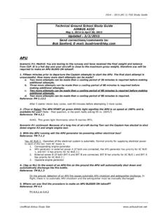
1 Datasheet_CSX_300_series_diesel_engine_s hutdown_system_0611_rev1_(CE235) CSX-300, 310 CSX-301, 311 Typical applicationsl Marine Engine safetyl Petrochemical industry safetyl Vacuum trucksl Cranes - both enginesl Land drilling rigsl Offshore equipment outside defined hazardous zonesl Road vehicles and tankersl Refinery equipmentl LNG plant equipmentKey features and benefitsl automatic intake valve shut down on Engine overspeed l Built-in contact relay for direct connection to Chalwyn SVX valvesl Splash resistant IP66 metal enclosurel Factory set voltage and high/low speed range inputsl Cable glands includedl 12 volt (CSX-300) or 24 volt (CSX-310) systems availablel Powered by existing Engine start batteryl Optional sensor circuit (in CSX-301 or CSX-311 versions) for shut down on low oil pressure and up to four temperature settingsDiesel Engine Shutdown System Model CSX-300l Can be tripped by gas detector added in series to normally closed sensor circuitl Precision overspeed trip speed setting via simple press button without overspeeding enginel Speed signal input from existing alternator or flywheel magnetic pickupl Manual Shutdown button available (optional)l System status indication on manual shut -down buttonl Meets Canadian regulations for safety near drilling rigsl Meets US BOEMRE regulations for safety on offshore platformsDatasheet_CSX_300_series_diesel _engine_shutdown_system_0611_rev1_(CE235 ) Diesel Engine Shutdown System - Series 300page 2 ENGINECUSTOMER'S12/24V ALTERNATORCONNECTION TO ENSURE POWER ISAVAILABLE WHEN IGNITION SWITCHIS IN THE RUN AND START POSITIONS ONLY50/25 AMP SUPPLY(FUSED BY CUSTOMER)1 AMP SUPPLYREQUIRED POWER SUPPLY+12/24 VOPTIONAL SENSORS (eg.)
2 PRESSURE & TEMPERATURE)(UP TO 5 OFF)CUSTOMER'S12/24V BATTERYEMERGENCY STOPTURN RELEASEM 20 NYLO NCABLE GLANDSYSTEMSTATUSLEDM16 NYLONCABLE GLANDM16 NYLONCABLE GLANDM20 NYLONCABLE GLANDM20 NYLONCABLE GLANDM16 NYLONCABLE GLANDCONTROL UNITCUSTOMER'SMAGNETIC PICKUPCUSTOMER'S SCREENED CABLEEARTHED AT Engine ENDORCUSTOMER'SALTERNATOR SPEED SIGNALIP67 CONNECTORSIP66 TRIP SPEED SETTING BUTTONCHALWYN FUEL SHUTOFF VA(OPTIONAL)CHALWYN SOLENOID OPERATEDAIR INTAKE Shutdown VALVE(POWER TO CLOSE)Chalwyn Series 300 (12 volt) and Series 310 (24 volt) systems monitor Engine speed to give an immediate Engine shut down by closure of an air intake valve if Engine overspeed is detected. Suitable for Engine and vehicle applications not requiring full hazardous area compliant speed signal is taken from the existing Engine alternator or flywheel magnetic pickup and is compared electronically with an easily programmed shut down setting. No calculations Descriptionor knowledge with respect to the drive ratio of the alternator or number of flywheel teeth is required.
3 The System also includes an optional stop button to enable manual emergency closure of the intake shut down up to 5 preset sensors can be supplied as part of the System to additionally give shut down on high Engine temperatures and/or low oil pressure. An automatic fuel shut down valve is also available if Layout Series 301 and 311 VALVED atasheet_CSX_300_series_diesel_engine_sh utdown_system_0611_rev1_(CE235) Diesel Engine Shutdown System - Series 300page 3 Chalwyn CSX-300 (12 volt) and CSX-310 (24 volt) Control BoxInputs/Outputs: On/off signal via Engine key switch circuit. Power from battery (via fuse) Speed signal from alternator or magnetic pick up Stop signal from emergency stop button. Run/stop signal from sensor circuit (where fitted) Power output to close intake shut down valveOverspeed trip setting: 20% above Engine speed at the time the trip speed setting button is operatedNumber of sensors in circuit: No more than 5 connected in seriesTime delay to establish oil pressure after Engine start: 15 seconds, following detection of a speed signal, before sensor circuit is monitored.
4 (No time delay for overspeed shut down function.)Trip speed setting range: Maximum setting - 17500 rpm (alternator speed) - 10000 rpm ( Engine speed using magnetic pickup and 100 tooth flywheel) Minimum setting - 2400rpm (alternator speed) - 960rpm ( Engine speed using magnetic pickup and 100 tooth flywheel) Factory setting - 6000 rpm (alternator speed) - 2400 rpm ( Engine speed using magnetic pickup and 100 tooth flywheel)Minimum speed at which System operates (not adjustable): - 800 rpm (alternator speed) - 320 rpm ( Engine speed using magnetic pickup and 100 tooth flywheel)Component DescriptionDie cast aluminium enclosure and lid complete with cable glands and meeting IP66. Contains the System micro-processor, associated electron-ics and terminal block. The overspeed trip speed setting button is accessed by removal of a pro-tective (CE235) Diesel Engine Shutdown System - Series 300page 4 Emergency Stop Button Assembly CSX-840 Chalwyn Air Intake shut Down Valves (12 volt) SVX-381, SVX-581 & SVX-881 (and 24 volt) SVX-391, SVX-591 & SVX-891 Select either the Series 300 or Series 310 to match the voltage used on the existing Engine whether the speed signal will be obtained from the Engine alternator (typically the W terminal) or the flywheel magnetic pick-up.
5 (The System will be configured at Chalwyn to suit the option selected.)Select the size of the air intake shut down valve required and determine whether it is to be mounted between flanges or inserted in the air intake hose using one of the range of Chalwyn Air Inlet Hose Adaptors (see publication CE228). Ensure that, at the position selected to mount the intake valve, easy and safe access to the manual reset lever will be Notes:The Series 300 and 310 systems will only give auto-matic shut down on Engine overspeed, operation of the emergency stop button or, where fitted, sensor trip or break in the sensor circuit. Other fault condi-tions, which may cause loss of the protection provided by the Series 300/310 System , will not generally give an automatic shut down. Instead a warning will be indicated by the System status LED in Series 300 and 310 systems are not suitable for defined hazardous area information on gas detectors that open the sensor circuit please contact Description continuedSlim butterfly valves of various diameters.
6 Manually latched open. Closed by powering the valve solenoid. Valve body and disc manufac-tured in corrosion resistant hard anodised alu-minium with PTFE coating. Spindle and mecha-nism made from stainless details of this range of shut down valves are given in Chalwyn publication FSX-200 automatic Fuel shut Down Valve and Fitting Kit FKX-300 (requires Y suffix added to SVX valve)The FSX-200 is designed to automatically close down at the same time as the air intake shut down valve. A manual reset is fitted to the FSX-200. This only requires reset after an auto-matic shut down or after a manual emergency shut down. Full details of FSX-200 are given in Chalwyn publication Temperature Switches TSX-100, TSX-135, TSX-150 and TSX-200 Immersion type temperature switches with hermetically sealed electrically isolated cases. Designed for monitoring coolant and exhaust temperatures. Standard settings are 100 C, 135 C, 150 C and 200 C, normally details of the Temperature Switch range are given in Chalwyn publications CE304 and Pressure Sensor PSX-010 Low oil pressure switch with electrically isolated body pre-set to bar/10psi (falling), normally open.
7 Full details of the PSX-010 are given in Chalwyn publication box incorporating the emergency stop button, System status light and cable entry gland. Degree of protection required, identify and order optional sensors or optional fuel shut down valve as part of the total optional item is recommended to give clear indication of System (CE235) Diesel Engine Shutdown System - Series 300page 5 Control UnitUsing the four M6 mounting holes in the base of the unit, mount the control unit to a sturdy plate using M6 x 20 fasteners. Ensure this mounting plate is supported and positioned to: a) Minimise vibration transmitted to the control unit. b) Give good access to the trip speed setting button without causing a hazard whilst the Engine is shut Down Valve1. In the case of a naturally aspirated Engine , the Chalwyn SVX shut down valve should gener-ally be fitted as close to the Engine air intake manifold as possible. If an air intake flame trap is also fitted, the SVX must be installed upstream (air cleaner side) of the flame If the Engine is turbocharged, fit the SVX downstream ( Engine side) of the turbocharger if space permits and the intake air tempera-ture is less than 150 C (302 F) as usually found downstream of the intercooler.
8 Any flame trap must be installed between the SVX and The SVX valve may be installed either horizon-tally or Ensure that the SVX Valve is installed such that safe access to the reset lever is possible and the electrical cables can be routed away clear of hot, sharp or moving Stop Button AssemblyUse two M4 fasteners to mount the assembly via the two holes in the base. Ensure the assembly is mounted such that:a) The stop button is easily accessibleb) The System status LED is always visible to the operator responsible for running the protected If hose adaptors are used, the mating hose should be of a reinforced type, provide adequate support for the valve and prevent excessive vibration. If necessary, additional support brackets mounted from the Engine should be Particular care must be taken to ensure the integrity of the intake pipework between the SVX valve and intake manifold. Ideally metal pipework should be used and any gaps kept as short as possible, taking into account any rela-tive movement, and closed by reinforced hose.
9 7. Any Engine crankcase breather connections into the intake System between the SVX valve and Engine , or any internal crankcase breather arrangement venting directly into the Engine intake ports must be sealed and replaced by an external breather System venting either to atmosphere or to the intake System upstream of the shut down valve. Note: Disconnect the wires between stop button assembly box and cover when mounting the (Mechanical) c) Enable the electrical cables to be routed away clear of hot surfaces and moving parts. d) Ensure that the control unit is not sub-ject to an effective ambient temperature exceeding 50 C (122 F).Datasheet_CSX_300_series_diesel_engin e_shutdown_system_0611_rev1_(CE235)Diese l Engine Shutdown System - Series 300page 6 Notes:a) After an automatic Engine shut down or an emergency manual shut down via the Series 300 / Series 310, the FSX-200 reset lever (see diagram) must be pulled in before restart. It is not necessary to reset the FSX-200 after a normal fuel shut down is used to stop the ) The fuel System pressure at the point of installation of the FSX-200 must not exceed 14 bar / 200 into the exhaust, coolant and oil pressure systems as appropriate.
10 Ensure the leads are connected in series and can be routed to the CSX Control Unit via the IP67 connectors avoid-ing hot, moving or sharp objects. FSX-200 Fuel shut Down ValveManual push to stop/pull to resetMounting holes (6 off)Connection to Intake System (1/8 BSP)Fuel In(3/8 BSP)Fuel Out(3/8 BSP)1. Install the FSX-200 into the fuel line as close as possible to the fuel injection pump. Support the FSX-200 using the mounting plate Locate the two 1/8 BSP holes tapped through the SVX air shut down valve body. Using thread sealant or thread locking compound: a) Tighten adaptor FKX-001 into the tapped hole on the Engine side of the shut down valve disc. b) Tighten blanking plug FKX-002 into the tapped hole on the body at air cleaner side of the SVX shut down valve Using the compression fittings and copper pipe supplied, connect the adaptor FKX-001 fitted in the air intake shut down valve to the fitting in the base of the FSX-200. Ensure all connections are leak free and that the copper pipe is suitably routed and clamped to avoid excessive vibration and/or automatic Fuel shut Down ValveOptional Intrinsically Safe SensorsDatasheet_CSX_300_series_diesel_e ngine_shutdown_system_0611_rev1_(CE235)D iesel Engine Shutdown System - Series 300page 7 1.