Transcription of Thermostatic Control Valves - AMOT
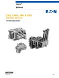
1 Thermostatic Control Valves Model HH ValveKey benefitsl No external power source required - simple, low cost installationl No user setting needed - fit and forget solutionl Small number of parts - simple maintenance and low cost of ownershipl Robust design capable of high vibration and shock applicationsl Easy installation, operates in any mounting positionl Automatic self-sensing Control with positive proportional valve actionTypical applications l Lubricating oil temperature controll Jacket water high temperature (HT)l Secondary water low temperature (LT)l Heat recoveryl Water saving applicationsl Boiler inlet temperature controll Co-generation, cooling towersl Temperature mixing or divertingl Engine and compressor cooling system availablel PED* Suitable for Group 1 & 2 liquids (Ensure materials are compatible) l ATEX* 11 2 G Xl * Complies with all relevant EU directivesKey featuresl Flow rates of 56 - 280m3/hr (245 - 1232 US gpm)l Combinations available: Housings in steel, stainless steell DN100 - DN150 (4 - 6 ) pipe sizel Flanged connectionsl Tamper-proof temperature settings from 13 C to 116 C (55 F to 240 F)l Pressure ratings: 45 bar (655 psi) 4 only 16 bar (230 psi)Datasheet_H_Thermostatic_Control_Val ve_0812_Rev4* Contact AMOT page 2 Thermostatic Control Valves - Model H Datasheet_H_Thermostatic_Control_Valve_0 812_Rev4 ContentsOverview.
2 3 Applications .. 4 Valve Characteristics .. 4 Pressure drop .. 5 Flow coefficient .. 6 Temperature & element characteristics .. 6 Available versions .. 6 How to order .. 7 Recommended spares .. 8 Specification .. 9 Dimensions .. 10 Weights .. 10page 3 Thermostatic Control Valves - Model H Datasheet_H_Thermostatic_Control_Valve_0 512_Rev3 OverviewAMOT model H Thermostatic Valves are available in a wide selection of sizes and settings to fill a multitude of fluid temperature Control requirements. These Valves may be mounted in any position and use the proven expanding wax principle to actuate the 3-way temperature element assemblies. The model H Valves may be used for diverting or mixing service. They make very economical temperature limiting Valves to prevent scalding in home, motel or hotel hot water supply systems. Radiant heating systems can use these Valves in limiting water temperature to prevent surface cracking and over-heating of plastic piping. Other applications include electronic and battery cooling circuits, pump temperature relief Valves etc.
3 LeakholesIn some applications, it is necessary to have leak holes drilled in the element to ensure a small flow between ports A and C. Leak holes are available in sizes ranging from to 19mm (1/4 to 3/4 ). Please refer to the Temperature Control Valve Temperature settingsA wide selection of element materials, seals, and temperatures are available. Follow the equipment manufacturers guidelines for heating/cooling systems. Temperature settings are available from 13 C to 116 C (55 F to 240 F). Refer to the Temperature & Element Characteristics table on page 6 for specific temperature settings. In general the temperature quoted is the nominal operating temperature in diverting mode on water systems. For long life, AMOT Valves should not be operated continuously at temperatures in excess of 14 C (25 F) of their maximum continuous rating. If this condition is anticipated then consult AMOT for suitable alternatives. Element materialsl Bronze, brass and stainless steell Nickel plated/Stainless steel Available housing materials l Steell Stainless steelFor mixing and oil circuits the temperature may be one to two degrees higher due to flow, viscosity and other system parameters.
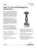
4 Elements and seals are available in a variety of materials. These materials are suitable for most applications. Please refer to the Temperature Control Valve Selection Guide (Datasheet_Temp_Control_Valve_Guide) for material compability Guide (Datasheet_Temp_Control_Valve_Guide) to determine the hole size required for specific materialsl Buna-N/Nitrilel Vitonpage 4 Thermostatic Control Valves - Model H Datasheet_H_Thermostatic_Control_Valve_0 812_Rev4 When Valves are used for diverting service, the inlet is Port A (temperature sensing port), with Port C being connected to the cooler, and Port B connected to the cooler by-pass ApplicationsApplicationsValve as shown maintains minimum flow through cooler to conserve water. Requires internal leak hole to permit small flow for Water Saving ApplicationsHeat loadAPumpPort blockedHeat removalAMOT thermostatHeat loadACBPumpBCWhen Valves are used for mixing service, Port C is the cold fluid inlet port from the cooler, Port B is the hot by-pass fluid inlet, and Port A the common outlet.
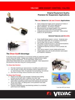
5 Port A is the temperature sensing port and will mix the hot and cold fluids in the correct proportion so as to produce the desired outlet temperature leaving Port ApplicationsHeat removalAMOT thermostatHeat loadPumpACBpage 5 Thermostatic Control Valves - Model H Datasheet_H_Thermostatic_Control_Valve_0 512_Rev3 - - 25 50 75 100 125 150 175 200 Pressurre Drop (Bar) Flow (m3/hr) H Valve Flow Chart ISO VG100 ISO VG46 WaterValve characteristicsPressure drop - Metric UnitsAMOT Thermostatic Valves are designed to produce minimal pressure drop. The normal recommendation in sizing the Valves is to select a pressure drop between to Bar (2 and 7 PSI).Pressure drop - English units - 1 2 3 4 5 6 7 8 9 1005010015020025030035040045050055060065 0700750800 Pressurre Drop (PSI) Flow (GPM) H Valve Flow Chart SAE 40 OilSAE 20 OilWaterValve4 H2550751001251501752005 H43851281712142562993426 H4693139185231278324370 Valve4 H 150 200 250 300 350 400 450500 550 600 650 700 750 8005 H 256 342 427 512 598 683 769854 939102511101196128113666 H 277 370 462 554 647 739 832924101611091201129413861478 Flow Rate for Water (US gpm)Flow Rate for Water (m3/hr)page 6 Thermostatic Control Valves - Model H Datasheet_H_Thermostatic_Control_Valve_0 812_Rev4 Flow coefficients (calculated)SizeKvCv4H2002325H4004646H40 0464 Flow coefficientValve characteristicsTemperature & element characteristicsSteel and stainless steel ANSI 150 lb flangesSteel and stainless steel ANSI 300 lb flanges 4 HOSJ4 HOSH4 HMSJ4 HMSH5 HOSJ5 HMSJ6 HOSJ6 HMSJA vailable versionsCodeControl rangeMax temp.
6 Cont. C FCrack openFull open C F C F C F0551355847206835 9507524752068308638100090329027813595431 1009535952985411054912010038 1003494421085012210541105 35954511355 13111043 110 381004711756 13311546115 40104501226114212049 120431105413066 15013054 130511246014068 15513557135541296314571 16014060 140571356615174 16515066 150631457216182 18015568 155661507416585 18516071 160681557817388 19016574 16571160791758819017077170741658318193 20017579 1757717085185102 21518082 1807917588191104 220195911958618898209107 22520596 20593200102215108 226215102 21598209107225115 239230110 230104219116239118 244240116 240108227122252123 254 QKvDP = SGKv is the flow coefficient in metric units. It is defined as the flow rate in cubic meters per hour (m /h) of water at a temperature of 16 Celsius with a pressure drop across the valve of 1 bar. The basic formula to find a valve s Kv is shown below:Q = Flow in US gallonsDP = Pressure drop (Psi)SG = Specific gravity of fluid (Water = )Cv = Valve flow coefficientQ = Cv DPSGQ = KvDPSGQ = Flow in m3/hrDP = Pressure drop (Bar)SG = Specific gravity of fluid (Water = )Kv = Valve flow coefficientCv is the flow coefficient in English units.
7 It is defined as the flow rate in US Gallons per minute (gpm) of water at a temperature of 60 Fahrenheit with a pressure drop across the valve of 1 psi. The basic formula to find a valve s Cv is shown below:2 QCvDP = SG2page 7 Thermostatic Control Valves - Model H Datasheet_H_Thermostatic_Control_Valve_0 512_Rev3 How to orderUse the tables below to select the unique specification of your H Code4 HOSH12003-0-AAValve Size4100 mm4"5125 mm5"6150 mm 6"Valve ModelHOStandardHMManual override Valve Body MaterialSSteelRStainless steelPort ConnectionJFlanged ANSI 150 lbHFlanged ANSI 300 lb (4" only)BFlanged PN10 CFlanged PN16 Control Temperature05513 C(55 F)07524 C(75 F)09032 C(90 F)09535 C(95 F)10038 C(100 F)11041 C(110 F)11543 C(115 F)12046 C(120 F)13054 C(130 F)13557 C(135 F)14060 C(140 F)15066 C(150 F)15568 C(155 F)16071 C(160 F)16574 C(165 F)17077 C(170 F)17579 C(175 F)18082 C(180 F)19591 C(195 F)20596 C(205 F)215102 C(215 F)230110 C(230 F)240116 C(240 F)Element & Seal Material019760X Standard element, Buna N O-rings029760P Nickel plated element and cage, Viton O-rings039760X Standard element and cage, Viton O-rings059760P Nickel plated element, Buna N O-Rings079844X Standard manual override element, Buna N O-Rings089844P Nickel plated manual override element and cage, Viton O-rings099844X Standard manual override element, Viton O-ringsLeakhole mm1/4" mm1/2"-D19 mm3/4"Customer Special Code-AAStandard Product-**Customer Special CodeLeakhole SizeCustomer Special RequirementsControl TemperatureValve SizeValve ModelPort ConnectionElement & Seal MaterialHousing Materialpage 8 Thermostatic Control Valves - Model H Datasheet_H_Thermostatic_Control_Valve_0 812_Rev4 Replacement parts include: Element O-ring Housing O-ring sealRecommended sparesModel HOWhen properly applied and installed, AMOT Thermostatic Valves should operate for years with minimal maintenance.
8 An inspection at two or three year intervals is adequate to detect and make provision for normal wear. The frequency of element replacement will depend on the operating conditions and the type of fluid being controlled. Because of the diaphragm and plug construction of the wax actuated element, calibration will be maintained over thousands of cycles. Whenever elements are replaced, the O-ring seals should also be replaced. For convenience, elements and O-ring seals may be ordered together in the service kits listed below. The parts may also be ordered individually by their part parts include: Element O-ring Housing O-ring seal, Buan N, Viton O-ring, stem seal, Buna N, VitonModel HM2 2 3 3 8 8 Ref (temp)1 or 2 Element assembly29760P (temp)1 or 2 Element assembly, plated29844 (temp)1 or 2 Element assembly, manual override311009L0011 or 2O-ring, element, Buna N (Std)311009L0021 or 2O-ring, element Viton811007L0011 or 2O-ring, housing, Buna N811007L0021 or 2O-ring, housing, Viton13111481 or 2O-ring, stem seal, Buna N1311148L0011 or 2O-ring, stem seal, Viton13 page 9 Thermostatic Control Valves - Model H Datasheet_H_Thermostatic_Control_Valve_0 512_Rev3 SpecificationFlow rate 56 to 280m3/hr (245 to 1232 US gpm)Recommended pressure to bar (2 to 7 PSI) dropBody materials Steel (BS.)
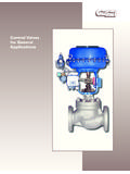
9 3100 A1, WCB) For high strength/pressure ratings Stainless steelSeal materials Nitrile VitonMounting position Any orientation Ports Below nominal temperature Ports A and B connected Above nominal temperature Ports A and C connectedPort connections ANSI flangesMaximum working pressures ANSI 150 lb 16 bar (230 psi) ANSI 300 lb 45 bar (655 psi) 4 valve only Valve size 100mm, 125mm and 150mm (4 , 5 and 6 ) (nominal bore) Control temperatures 13 C to 116 C 55 F to 240 F See element characteristics tableAccreditations* PED Suitable for Group 1 & 2 liquids. (Ensure materials are compatible.) ATEX 11 2 G X Complies with all relevant EU directives* Contact AMOT page 10 Thermostatic Control Valves - Model H Datasheet_H_Thermostatic_Control_Valve_0 812_Rev4 Valve dimensionsWeight Weights in kg (lbs)A = Inlet portB = Bypass portC = Cooler portDimension (mm)4 HOSJ/ HMSJ4 HOSH/ 4 HMSH5 HOSJ/ 5 HMSJ6 HOSJ/ HMSJN ominal (HM only)178178184194 Model HO and HMFlange drilling (mm)Flange4 HOSJ/ HMSJ4 HOSH/ 4 HMSH5 HOSJ/ 5 HMSJ6 HOSJ/ HMSJd19222222K191198216241n8888 Angular Material4 HOSJ/ 4 HMSJ4 HOSH/ 4 HMSH5 HOSJ/ 5 HMSJ6 HOSJ/ 6 HMSJW eight68 (150)68 (150)91 (200)120 (265)Dimensions (mm) , Middle East and AfricaAMOTW estern WayBury St EdmundsSuffolk, IP33 3 SZEnglandTel +44 (0) 1284 762222 Fax +44 (0) 1284 760256 Email Controls GmbHRondenbarg 2522525 HamburgGermanyTel +49 (0) 40 8537 1298 Fax +49 (0)
10 40 8537 1331 Email Russia#34 Shabolovka StreetBuilding 2 Moscow 115419 RussiaTel +7 495 617 12 93 Fax +7 495 913 97 65 Email USA8824 Fallbrook DrHouston, TX 77064 USATel +1 (281) 940 1800 Fax +1 (713) 559 9419 Email general: orders: customer service: and AustralasiaAMOT ShanghaiRm 4102 - 4104 United Plaza1468 Nanjing Road WestShanghai 200040 ChinaTel +86 (0) 21 6279 7700 Fax +86 (0) 21 5237 8560 Email Singapore10 Eunos Road 8 #12-06 Singapore Post CentreSingapore 408600 Tel +65 6408 6265 Fax +65 6293 3307 Email