Transcription of Vickers Valves CM2, CM11, RM3 & FM3 Control Valves
1 303 Revised 4/96CM2, cm11 , RM3 & FM3 Control ValvesFor Mobile EquipmentVickers Valves 2 IntroductionThe directional Valves described in thisbooklet are more than just directionalvalves -- they are hydraulic controlsystems. Their function is to controldirection of flow, rate of flow the use of various valvecircuitry, logic circuitry can be providedfor automatic sequencing operations can be eitherpressure or position-actuated. Vickersvalves are also designed to permit theoperation of many functions from asingle pumping source. These and themany other features provide the building blocks for a Control system forany piece of mobile has the worldwide facilities andskilled personnel to give you qualityproducts, prompt delivery, plusapplication and service assistance.
2 Youcan depend on Vickers for the finesthydraulic products and Section Directional ValvesCM2 and cm11 SeriesGeneral Description3.. Benefits4.. System Relief Valve5.. Cylinder Port Valving5.. Inlet Sections5.. Outlet Sections8.. Narrow Bypass Sections9.. Spools9.. Spool Symbols10.. Spool Orientation10.. Spool Detents10.. Detent Conversion Kit10.. Optional Centering Springs10.. Hydraulic Actuators10.. Electric Switch11.. Electric Switch Conversion Kit11.. Two-pressure System11.. Lever Linkage Adapter11.. Lever Kits12.. Mixture of Port Sizes12.. Dust Covers12.. Viton Seals12.. Specifications12.. Typical Performance12.. Performance Data Curves13.. Installation DimensionsCM2 Series14.. cm11 Series18.. Model CodesCM2 Series22.
3 cm11 Series23.. Pressure and Flow Control ValvesRM3 and FM3 SeriesDescription24.. Performance Curves24.. Installation Dimensions25.. Model Code26.. Application Guidelines26.. 3 Multiple Section Directional ValvesGeneral DescriptionThese manually and hydraulicallyactuated, spring centered, spool typevalves are designed for pressures up to210 bar (3000 psi) and flows up to 265l/min (70 USgpm). They are comprisedof sections that are internally connectedto common pressure and tank returnpassages. Seals between the sectionsseal the connecting passages, and thesections are held together by studs sections are available asassembled banks, and as separatesections for customers to assemble intobanks or to add to or change thefunctions of a bank.
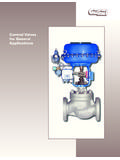
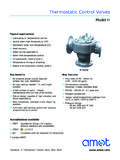
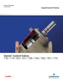
4 The followingillustration shows the construction andassembly of a three-section StudCheckValveCam 4 Multiple Section Directional ValvesEnd sections of multiple-spool valvescontain the inlet or outlet porting and aspool. Eight spools can be addedbetween end sections for a maximum often operating sections per valve single-spool Valves the spool islocated in the inlet end section, and ano-spool outlet plate is following illustration shows the inletand outlet ports and the bypass,pressure and tank passages of a typicalthree-section valve. The pressurepassage carries fluid to cylinder portswhen the spools are shifted. The bypasspassage permits flow directly to theoutlet when the spools re not beingoperated. The tank passage also carriesfluid to the outlet; either return flow fromthe cylinder ports or fluid diverted pastthe flow Control and relief are shown in the centered orneutral position.
5 Under these conditions,fluid in the pressure passage is blockedfrom cylinder ports by the spool through the valve is through thebypass and tank passages to the Valve Sensing OrificeBypass Flow Control OrificePressure PassageFlow Control & Relief ValveCylinder PortsTank PassageBypass PassageOutCenterInInletOutlet T B D When a spool is shifted, flow is asdescribed in the spools section onpage sectional Valves have internal parallelcircuitry. All pump flow can be used forany one work function. If two or morespools are shifted simultaneously, flowwill go to the function requiring thelowest pressure. Flow can be controlledto multiple functions by metering banks can be connected inparallel or series-parallel.
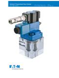
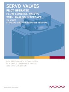
6 Spools in thesecond bank can be operated whenspools in the first bank are in the neutralor operating leakage selective fitImprovedmetering fromcylinder to tankportOutstanding meteringfrom pressure tocylinder portsIntegral checks onevery valve sectionprevent cylinderbacksliding with theloadExtra largeinternalpassagesEach valve section, except those with a B spool, includes a load-drop checkvalve to prevent a load from droppingwhen an operating spool is shifted. Aload-drop check can be provided in B spool sections for special Operation Vickers manuallyoperated sectional Valves offer absolutesmoothness both in raising and loweringloads. In addition to outstandingmetering from pressure to cylinder ports,they have equally precise meteringcapability from cylinder to tank Work Capacity Littlehorsepower is consumed in the valvedue to low pressure drop.
7 On manyengine-powered vehicles this gives thepotential for low heat rise from valvehydraulic flow losses in areas whereexcess heat may already be a electric battery-powered vehicles,valuable amphere hours are savedbecause energy wasted through heatloss is reduced. More fluid power isavailable to perform and Service Flexibility Multiple section design providesinstallation and service flexibility. Valvescan be maintained or modified readilyand at low cost in the field. Three-pointmounting aids installation stability whenthe valve is mounted on an Sectional DesignHigh Strength Castings Cast ironvalve bodies reduce deflection so thateven under the most arduous operatingconditions there is no spool bind frompressure.
8 Internal passages areshell-cored to provide streamlinedhydraulic passages for minimumpressure O ringseal betweensections ofspacer platesreducesstresses,permits fulcrumon each valvesection forrigidityHigh strength iron casting reducesinternal stresses, insures smoothoperation of spoolIntegral System Protection Anintegral cartridge type relief valve isprovided in the valve inlet for systemprotection. Pressure settings are presetto your specifications to providetamper-free 5 Multiple Section Directional ValvesSystem Relief Valve R and K inlet sections are providedwith an integral, cartridge type reliefvalve for system protection. Crackingpressure is preset to your are available from 35-210 bar(500-3000 psi) in increments of 17 bar(250 psi).
9 Tamperproof relief valve preset from35-210 bar (500-3000 psi), in 17 bar(250 psi) incrementsProduction-proved,pilot operated relief valveExternally Vented System ReliefValve This cm11 valve option consistsof a tapped hole in the SAE plug whichholds the relief valve in its bore. Thisfeature thus provides a means forremotely diverting pump flow to tank tounload the Adjustable System ReliefValve An externally adjustable systemrelief valve is available for CM2 andCM11 Valves . This option is provided byadding a second, externally adjustablepilot stage to Control the systempressure at which the main relief shiftsand directs pump flow to tank. Thesecond pilot stage is adjustable tocontrol system pressure up to 17 bar(250 psi) below the main relief effect, the standard relief valve pilotstage acts as a safety limit.
10 Theoperator cannot exceed the vehicle smaximum intended load rating. Theoptional adjustment feature, however,allows simple adjustment of systempressure after the valve is installed inthe vehicle and under actual load-liftingconditions. It also permits adjustment forminimum pressure to meet vehicleratings, for example, providing a meansto obtain the lowest possible currentdraw on electrically powered lift to the following Port ValvingCM2 directional Valves are availablewith any combination of cylinder portprefill check or relief Valves as shown inthe model code on page 22. The portrelief Valves prevent excessive pressurein cylinder or actuator lines when thedirectional valve spool is in the neutralposition. The port also acts as ananti-cavitation and prefill check pressure in the cylinder port isless than pressure in the return line, thecheck valve allows return oil to replenishthe system.