Transcription of Discovery kit with STM32F407VG MCU - st.com
1 May 2017 DocID022256 Rev 61/341UM1472 User manualDiscovery kit with STM32F407VG MCUI ntroductionThe STM32F4 Discovery Discovery kit allows users to easily develop applications with the STM32F407VG high performance microcontroller with the ARM Cortex -M4 32-bit core. It includes everything required either for beginners or for experienced users to get quickly on STM32F407VG , it includes an ST-LINK/V2 or ST-LINK/V2-A embedded debug tool, two ST-MEMS digital accelerometers, a digital microphone, one audio DAC with integrated class D speaker driver, LEDs, push buttons and a USB OTG micro-AB connector. To expand the functionality of the STM32F4 Discovery Discovery kit with the Ethernet connectivity, LCD display and more, visit the webpage. The STM32F4 Discovery Discovery kit comes with the STM32 comprehensive free software libraries and examples available with the STM32 Cube package, as well as a direct access to the ARM mbed Enabled on-line resources at 1.
2 STM32F4 DISCOVERY1. Picture is not Rev 6 Contents1 Features .. 62 Product marking .. 73 Ordering information .. 74 Conventions .. 75 Quick start .. started .. requirements .. toolchains supported .. 86 Hardware and layout .. ST-LINK/V2 (or V2-A) .. (or V2-A) firmware upgrade .. VCP configuration .. ST-LINK/V2 (or V2-A) to program/debug the STM32F407VG on board .. ST-LINK/V2 (or V2-A) to program/debug an external STM32 application .. supply and power selection .. buttons .. audio capability .. OTG supported .. sensor (ST-MEMS LIS302DL or LIS3 DSH) .. (Idd) .. clock .. clock supply .. 32 KHz clock supply .. bridges .. connectors .. 19 DocID022256 Rev 63/34UM1472 Contents37 Electrical schematics .. 268 Mechanical drawing .. 329 Revision history .. 33 List of tablesUM14724/34 DocID022256 Rev 6 List of tablesTable of the order codes .. 7 Table conventions.
3 7 Table states .. 12 Table connector CN2 (SWD) .. 15 Table bridges.. 19 Table pin description versus board functions .. 20 Table revision history .. 33 DocID022256 Rev 65/34UM1472 List of figures5 List of figuresFigure .. 1 Figure block diagram .. 9 Figure top layout .. 10 Figure bottom layout .. 11 Figure composite device .. 12 Figure VCP connection to USART2 .. 13 Figure connections .. 14 Figure connections .. 15 Figure .. 26 Figure (SWD only) .. 27 Figure .. 28 Figure .. 29 Figure .. 30 Figure .. 31 Figure mechanical drawing .. 32 FeaturesUM14726/34 DocID022256 Rev 61 FeaturesThe STM32F4 Discovery offers the following features: STM32F407 VGT6 microcontroller featuring 32-bit ARM Cortex -M4 with FPU core, 1-Mbyte Flash memory, 192-Kbyte RAM in an LQFP100 package On-board ST-LINK/V2 on STM32F4 Discovery or ST-LINK/V2-A on STM32F407G-DISC1 ARM mbed Enabled ( ) with ST-LINK/V2-A only USB ST-LINK with re-enumeration capability and three different interfaces: Virtual COM port (with ST-LINK/V2-A only) Mass storage (with ST-LINK/V2-A only) Debug port Board power supply: Through USB bus External power sources:3 V and 5 V LIS302DL or LIS3 DSH ST MEMS 3-axis accelerometer MP45DT02 ST MEMS audio sensor omni-directional digital microphone CS43L22 audio DAC with integrated class D speaker driver Eight LEDs.
4 LD1 (red/green) for USB communication LD2 (red) for V power on Four user LEDs, LD3 (orange), LD4 (green), LD5 (red) and LD6 (blue) 2 USB OTG LEDs LD7 (green) VBUS and LD8 (red) over-current Two push buttons (user and reset) USB OTG FS with micro-AB connector Extension header for all LQFP100 I/Os for quick connection to prototyping board and easy probing Comprehensive free software including a variety of examples, part of the STM32 CubeF4 package or STSW-STM32068 for legacy standard library usageDocID022256 Rev 67/34UM1472 Product marking332 Product markingTools marked as "ES" or "E" are not yet qualified and as such, they may be used only for evaluation purposes. ST shall not be liable for any consequences related with other ways of use of such non-qualified tools, for example, as reference design or for of location of "E" or "ES" marking: On target STM32 microcontroller part mounted on the board (for illustration, refer to section Package information of a STM32 datasheet at ).
5 Next to the evaluation tool ordering part number, as a label stuck or a silk-screen printed on the Ordering informationTo order the Discovery kit for the STM32F407 line of microcontrollers, refer to Ta b l e 1. 4 Conventions Ta b l e 2 provides the definition of some conventions used in the present document. Table 1. List of the order codes Order codeST-LINK versionSTM32F4 DISCOVERYST-LINK/V2 STM32F407G-DISC1ST-LINK/V2-A (mbed Enabled)Table 2. ON/OFF conventions Convention Definition Jumper JP1 ON Jumper fittedJumper JP1 OFF Jumper not fittedSolder bridge SBx ON SBx connections closed by solder Solder bridge SBx OFF SBx connections left open Quick startUM14728/34 DocID022256 Rev 65 Quick startThe STM32F4 Discovery is a low-cost and easy-to-use development kit to quickly evaluate and start a development with an STM32F407VG high-performance installing and using the product, accept the Evaluation Product License Agreement from the more information on the STM32F4 Discovery and for demonstration software, visit the Getting started Follow the sequence below to configure the STM32F4 Discovery board and launch the DISCOVER jumper position on the board, JP1 on, CN3 on ( Discovery selected).
6 2. Connect the STM32F4 Discovery board to a PC with a USB cable type A to mini-B through USB connector CN1 to power the board. Red LED LD2 (PWR) then lights Four LEDs between B1 and B2 buttons are Press user button B1 to enable the ST MEMS sensor, move the board and observe the four LEDs blinking according to the motion direction and speed. (If a second USB cable type A to micro-B is connected between PC and CN5 connector, then the board is recognized as standard mouse and its motion will also control the PC cursor).5. To study or modify the DISCOVER project related to this demonstration, visit the webpage and follow the Discover the STM32F407VG features, download and execute programs proposed in the list of Develop the application using available System requirements Windows OS (XP, 7, 8 and 10), Linux 64-bit or macOS USB type A to Mini-B Development toolchains supported Keil MDK-ARM(a) IAR EWARM(a) GCC-based IDEs including free SW4 STM32 from AC6 ARM mbed Enabled onlinea.
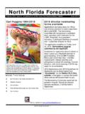
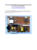
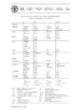
7 On Windows Rev 69/34UM1472 Hardware and layout336 Hardware and layout The STM32F4 Discovery is designed around the STM32F407 VGT6 microcontroller in a 100-pin LQFP package. Figure 2 illustrates the connections between the STM32F407 VGT6 and its peripherals (ST-LINK/V2 or ST-LINK/V2-A, push buttons, LEDs, Audio DAC, USB, ST-MEMS accelerometer and microphone, and connectors). Figure 3 and Figure 4 help users to locate these features on the STM32F4 Discovery board. Figure 2. Hardware block diagram 06Y 9 &6 / % 86(5, 20 LQL86%/' WR /' % 5675(6(7, 2, 2+HDGHU6:'/,6 '6+ RU /,6 '6+(PEHGGHG67 /,1. 9 RU 67 /,1. 9 $670 ) 9*7 0 LFUR 86%03 '7 /('0 LQL -DFN+HDGHUH ardware and layoutUM147210/34 DocID022256 Rev 6 Figure 3. STM32F4 Discovery top layout Note:Pin 1 of CN2, CN3, JP1, P1 and P2 connectors are identified by a red square. 3 5 5 5 /' &1 % 5 & & & 5 & & / 5 8 & 5 5 5 &1 & 5 /' & 5 5 5 5 /' 5 & & 8 &1 5 5 & & 8 & /' 5 5 5 5 & 5 5 8 5 5 5 8 5 ' & & & & 5 5 -3 5 5 & 5 & 5 5 & & & 5 & 5 /' 5 & 5 & 3:5& & ' 5 5 5 & & 5 8 & 67 /, ' 3' 3% 3% 3( *1'3$ 3& &1 1&3' 3( 3% 3$ 3& 8 5 ' & & & 5 5 5 5 & /' & 5 8 5 & 8 & 7 & 5 /' 5 5 5 /' 5 % & 5 3& & 3' 3% & 3( 5 3+ 5 &1 3 *1'3' 3' 3% 3( 3( 3( 3% 3& 3$ 3$ 3& 3$ 9''*1'3' *1'3' 3' 3% 3% 3( 3( 3% 3& 3$ 3$ 3$ 3& *1'9''& & 8 VHU,GG& 5 &205 & & & & 5 5 & & 5 5 5 6% & & & *1'3& 3$ 3' 3' 3' 3% 3( 3( 3( 9*1' 93( *1'6:'3( 3% 15673% 9',6&29(5< 9& 3$ 5 HVHW3& 3$ 3' 3% 3( 3+ 3$ 3& %227 3& *1'3& 3$ 3$ 3' 3' 3' 3% 9''3% 3( 3( 3& 3& *1'3& 3% 3& ZZZ VW FRP VWP I GLVFRYHU\0% 06 9 /' UHG JUHHQ /(' &20&1 6:' FRQQHFWRU-3 ,'' PHDVXUHPHQW67 /,1.))))))))))))))))))))))
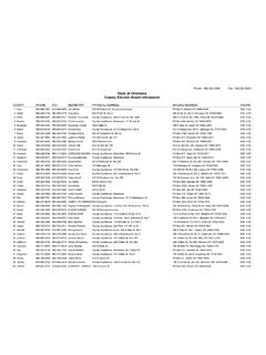
8 9 9 SRZHUVXSSO\ RXWSXW 9 SRZHUVXSSO\ LQSXW RXWSXW6% % 5(6(7 670 ) 9*7 % XVHU EXWWRQ% UHVHW EXWWRQ /' RUDQJH /(' JUHHQ /(' /' /' UHG /(' 3:5&1 67 /,1. ',6&29(5<VHOHFWRU EOXH /(' /' /' UHG /(' JUHHQ /(' /' /' UHG /(' '670 ) * ',6& DocID022256 Rev 611/34UM1472 Hardware and layout33 Figure 4. STM32F4 Discovery bottom layout Embedded ST-LINK/V2 (or V2-A) ST-LINK/V2 on STM32F4 Discovery or ST-LINK/V2-A on STM32F407G-DISC1 is an embedded tool for programming and debugging. The embedded ST-LINK/V2 (or V2-A) supports only SWD for STM32 devices. For information about debugging and programming features refer to ST-LINK/V2 in-circuit debugger/programmer for STM8 and STM32, UM1075 User manual, which describes in details all the ST-LINK/V2 features. The changes on ST-LINK/V2-A versus ST-LINK/V2 version are listed below. New features supported on ST-LINK/V2-A: Virtual COM port interface on USB (see Section : ST-LINK/V2-A VCP configuration) Mass storage interface on USB3" 3" 3" 3" -3 6 3" 3" 3" 3" 2%3%26%$ $%&!))))))))
9 5,4 3" " 53%2 3" 6$$ FROM 6 3" "//4 3" .234 3" "//4 3" 34-?234 3" 8 CRYSTAL 3" 8 CRYSTAL 3" 8 CRYSTAL 3" 8 CRYSTAL 3" 37/ Hardware and layoutUM147212/34 DocID022256 Rev 6 Features not supported on ST-LINK/V2-A: SWIM interface Minimum supported application voltage limited to 3 V USB power management request for more than 100 mA power on USBK nown limitation: Activating the readout protection on ST-LINK/V2-A target, prevents the target application from running afterwards. The target readout protection must be kept disabled on ST-LINK/V2-A boards. There are two different ways to use the embedded ST-LINK/V2 (or V2-A) depending on the jumper states (see Table 3): Program/debug the STM32 on board (refer to Section : Using ST-LINK/V2 (or V2-A) to program/debug the STM32F407VG on board) Program/debug the STM32 in an external application board, using a cable connected to SWD connector CN2 (refer to Section : Using ST-LINK/V2 (or V2-A) to program/debug an external STM32 application) Drivers Before connecting the STM32F4 Discovery board to a Windows PC (XP, 7, 8 and 10) through the USB, a driver for the ST-LINK/V2 (or V2-A) must be installed.
10 It is available at the website. In case the STM32 Discovery is connected to the PC before the driver is installed, some Discovery interfaces may be declared as Unknown in the PC device manager. To recover from this situation, after installing the dedicated driver, the association of Unknown USB devices found on the STM32F4 Discovery board to this dedicated driver, must be updated in the device manager :It is recommended to proceed by using USB Composite Device, as shown in Figure 5. Figure 5. USB composite deviceTable 3. Jumper states Jumper state Description Both CN3 jumpers ON ST-LINK/V2 (or V2-A) functions enabled for on board programming (default) Both CN3 jumpers OFF ST-LINK/V2 (or V2-A) functions enabled for application through external CN2 connector (SWD supported)DocID022256 Rev 613/34UM1472 Hardware and ST-LINK/V2 (or V2-A) firmware upgrade The ST-LINK/V2 (or V2-A) embeds a firmware upgrade mechanism for in-situ upgrade through the USB port.