Transcription of DRV8711 Stepper Motor Controller IC datasheet (Rev. H)
1 Product Order Technical Tools & Support & Reference Folder Now Documents Software Community Design DRV8711 . SLVSC40G JUNE 2013 REVISED MAY 2017. DRV8711 Stepper Motor Controller IC. 1 Features 3 Description 1 Pulse Width Modulation (PWM) Microstepping The DRV8711 device is a Stepper Motor Controller Motor Driver that uses external N-channel MOSFETs to drive a bipolar Stepper Motor or two brushed DC motors. A. Built-In 1/256-Step Microstepping Indexer microstepping indexer is integrated, which is capable Drives External N-Channel MOSFETs of step modes from full step to 1/256-step. Optional STEP/DIR Pins An ultra-smooth motion profile can be achieved using Optional PWM Control Interface for DC Motors adaptive blanking time and various current decay Flexible Decay Modes, Including Automatic Mixed modes, including an auto-mixed decay mode.
2 Motor Decay Mode stall is reported with an optional back-EMF output. Stall Detection With Optional BEMF Output A simple step/direction or PWM interface allows easy interfacing to Controller circuits. A SPI serial interface Highly Configurable SPI Serial Interface is used to program the device operation. Output Internal Reference and Torque DAC current (torque), step mode, decay mode, and stall 8-V to 52-V Operating Supply Voltage Range detection functions are all programmable through a Scalable Output Current SPI serial interface. Thermally Enhanced Surface-Mount Package Internal shutdown functions are provided for 5-V Regulator Capable of 10-mA Load overcurrent protection, short-circuit protection, undervoltage lockout, and overtemperature.
3 Fault Protection and Diagnostic Features conditions are indicated through a FAULTn pin, and Overcurrent Protection (OCP) each fault condition is reported through a dedicated Overtemperature Shutdown (OTS) bit through SPI. Undervoltage Lockout (UVLO) The DRV8711 is packaged in a PowerPAD 38-pin Individual Fault Condition Indication Bits HTSSOP package with thermal pad (Eco-friendly: RoHS and no Sb/Br). Fault Condition Indication Pin Device Information(1). 2 Applications PART NUMBER PACKAGE BODY SIZE (NOM). Office Automation Machines DRV8711 HTSSOP (38) mm mm Factory Automation (1) For all available packages, see the orderable addendum at Textile Machines the end of the data sheet.
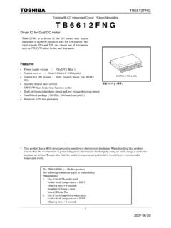
4 Robotics Simplified Schematic V to 52 V. STEP DRV8711 Gate Drive +. N-Channel MOSFETs DIR. M. MCU. SPI Stepper - SLEEPn Motor Sense + - Pre-Driver nFAULT. 1/256. step 1. An IMPORTANT NOTICE at the end of this data sheet addresses availability, warranty, changes, use in safety-critical applications, intellectual property matters and other important disclaimers. PRODUCTION DATA. DRV8711 . SLVSC40G JUNE 2013 REVISED MAY 2017 Table of Contents 1 Features .. 1 Programming .. 25. 2 Applications .. 1 Register Maps .. 26. 3 Description .. 1 8 Application and Implementation .. 30. 4 Revision 2 Application 30. Typical Application .. 30. 5 Pin Configuration and Functions.
5 3. 6 5 9 Power Supply 34. Bulk Capacitance .. 34. Absolute Maximum Ratings .. 5. ESD Ratings .. 5 10 35. Recommended Operating 5 Layout Guidelines .. 35. Thermal Information .. 5 Layout Example .. 36. Electrical 6 11 Device and Documentation Support .. 37. SPI Timing Requirements .. 7 Documentation Support .. 37. Indexer Timing 8 Receiving Notification of Documentation Updates 37. Typical Characteristics .. 9 Community 37. 7 Detailed Description .. 10 Trademarks .. 37. Overview .. 10 Electrostatic Discharge Caution .. 37. Functional Block Diagram .. 11 Glossary .. 37. Feature 12 12 Mechanical, Packaging, and Orderable Device Functional 25 Information .. 37.
6 4 Revision History NOTE: Page numbers for previous revisions may differ from page numbers in the current version. Changes from Revision F (July 2016) to Revision G Page Changed the description of the SCS pin in the Pin Functions table .. 3. Changed the maximum voltages for the charge pump voltage, high-side gate drive pin voltage, and phase node pin voltage in the Absolute Maximum Ratings table .. 5. Changed the OTS bit description in the STATUS register .. 29. Clarified UVLO bit operation when device is sleep mode .. 29. Changes from Revision E (March 2015) to Revision F Page Clarified that the SMPLTH bit 10 is a write-only bit in the TORQUE register .. 22.
7 Changed the default values for the OCPTH, OCPDEG, IDRIVEN, and IDRIVEP bits in the DRIVE register .. 28. Added the Receiving Notification of Documentation Updates and Community Resources sections .. 37. Changes from Revision D (January 2014) to Revision E Page Added ESD Ratings table, Feature Description section, Device Functional Modes, Application and Implementation section, Power Supply Recommendations section, Layout section, Device and Documentation Support section, and Mechanical, Packaging, and Orderable Information section .. 1. Changes from Revision C (December 2013) to Revision D Page Changed STATUS Register bit descriptions 3 through 5 .. 29. 2 Submit Documentation Feedback Copyright 2013 2017, Texas Instruments Incorporated Product Folder Links: DRV8711 .
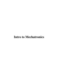
8 DRV8711 . SLVSC40G JUNE 2013 REVISED MAY 2017. 5 Pin Configuration and Functions DCP PowerPAD Package 38-Pin HTSSOP. Top View CP1 1 38 GND. CP2 2 37 AOUT1. VCP 3 36 A1HS. VM 4 35 A1LS. GND 5 34 AISENP. V5 6 33 AISENN. VINT 7 32 A2LS. SLEEPn 8 31 A2HS. RESET 9 30 AOUT2. GND GND. STEP / AIN1 10 29. DIR / AIN2 11 (PPAD) 28 BOUT1. BIN1 12 27 B1HS. BIN2 13 26 B1LS. SCLK 14 25 BISENP. SDATI 15 24 BISENN. SCS 16 23 B2LS. SDATO 17 22 B2HS. FAULTn 18 21 BOUT2. STALLn / BEMFVn 19 20 BEMF. Pin Functions PIN. I/O (1) DESCRIPTION EXTERNAL COMPONENTS OR CONNECTIONS. NAME NO. POWER AND GROUND. 5, 29, GND 38, Device ground All pins must be connected to ground PPAD. Connect to Motor supply voltage.
9 Bypass to GND with a F. VM 4 Bridge A power supply ceramic capacitor plus a 100- F electrolytic capacitor. Logic supply voltage. Bypass to GND with a 1- F X7R ceramic VINT 7 Internal logic supply voltage capacitor. 5-V linear regulator output. Bypass to GND with a F 10-V X7R. V5 6 O 5-V regulator output ceramic capacitor. CP1 1 IO Charge pump flying capacitor Connect a F X7R capacitor between CP1 and CP2. Voltage CP2 2 IO Charge pump flying capacitor rating must be greater than applied VM voltage. VCP 3 IO High-side gate drive voltage Connect a 1- F 16-V X7R ceramic capacitor to VM. CONTROL. SLEEPn 8 I Sleep mode input Logic high to enable device, logic low to enter low-power sleep mode Indexer mode: Rising edge causes the indexer to move one step.
10 STEP/AIN1 10 I Step input/Bridge A IN1. External PWM mode: controls bridge A OUT1 Internal pulldown. Indexer mode: Level sets the direction of stepping. DIR/AIN2 11 I Direction input/Bridge A IN2. External PWM mode: controls bridge A OUT2 Internal pulldown. Indexer mode: No function BIN1 12 I Bridge B IN1. External PWM mode: controls bridge B OUT1 Internal pulldown. Indexer mode: No function BIN2 13 I Bridge B IN2. External PWM mode: controls bridge B OUT2 Internal pulldown. Active-high reset input initializes all internal logic and disables the H- RESET 9 I Reset input bridge outputs. Internal pulldown. SERIAL INTERFACE. Active high to enable serial data transfer.