Transcription of MAX13487E/MAX13488E Half-Duplex RS-485-/RS-422- …
1 MAX13487E/MAX13488 EHalf-Duplex RS-485-/RS-422- Compatible Transceiver withAutoDirection ControlEVALUATION KIT AVAILABLEG eneral DescriptionThe MAX13487E/MAX13488E +5V, Half-Duplex , 15kVESD-protected RS-485/RS-422-compatible transceiversfeature one driver and one receiver. The MAX13487E/MAX13488E include a hot-swap capability to eliminatefalse transitions on the bus during power-up or liveinsertion. The MAX13487E/MAX13488E feature Maxim s propri-etary AutoDirection control. This architecture makes thedevices ideal for applications, such as isolated RS-485ports, where the driver input is used in conjunction withthe driver-enable signal to drive the differential MAX13487E features reduced slew-rate driversthat minimize EMI and reduce reflections caused byimproperly terminated cables, allowing error-free trans-mission up to 500kbps. The MAX13488E driver slewrate is not limited, allowing transmit speeds up to16 Mbps.
2 The MAX13487E/MAX13488E feature a 1/4-unit loadreceiver input impedance, allowing up to 128 trans-ceivers on the bus. These devices are intended for Half-Duplex communications. All driver outputs areprotected to 15kV ESD using the Human Body MAX13487E/MAX13488E are available in an 8-pinSO package. The devices operate over the extended -40 C to +85 C temperature RS-485 InterfacesUtility MetersIndustrial ControlsIndustrial Motor DrivesAutomated HVAC SystemsBenefits and Features AutoDirection Saves Space and BOM Cost AutoDirection Enables Driver Automatically on Transmission, Eliminating an Opto or Other Discrete Means of Isolation 8-Pin SO Package Robust Protection Features for Telecom, Industrial,and Isolated Applications Hot-Swap Capability to Eliminate False Transitionson the Bus During Power-Up or Live Insertion Extended ESD Protection for RS-485 I/O Pins( 15kV Human Body Model) Options Optimize Designs for Speed or ErrorlessData Transmission Enhanced Slew-Rate Limiting Facilitates Error-Free Data Transmission (MAX13487E) High-Speed Version (MAX13488E)
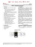
3 Allows forTransmission Speeds Up to 16 Mbps 1/4-Unit Load, Allowing Up to 128 Transceivers onthe BusOrdering Information/Selector GuidePARTPIN-PACKAGESLEW-RATELIMITEDMAX1 3487 EESA+8 SOYesMAX13488 EESA+8 SONo+Denotes a lead(Pb)-free/RoHS-compliant :All devices operate over the -40 C to +85 C Configuration/Typical Application Circuit appear at endof data ++-STATEMACHINEDRABREDIROCOMDEREGNDSHDN1 324675 RIDIVDTMAX13487 EMAX13488 EFunctional Diagram19-0740; Rev 1; 2/15 MAX13487E/MAX13488 EHalf-Duplex RS-485-/RS-422- Compatible Transceiver withAutoDirection ControlMaxim Integrated | Maximum RatingsStresses beyond those listed under Absolute Maximum Ratings may cause permanent damage to the device. These are stress ratings only, and functionaloperation of the device at these or any other conditions beyond those indicated in the operational sections of the specifications is not implied. Exposure toabsolute maximum rating conditions for extended periods may affect device reliability.
4 (All voltages referenced to GND.)Supply Voltage +6 VSHDN, RE, to +6A, -8V to +13 VShort-Circuit Duration (RO, A, B) to GND ..ContinuousContinuous Power Dissipation (TA= +70 C)8-Pin SO (derate C above +70 C)..471mWOperating Temperature Range ..-40 C to +85 CJunction Temperature ..+150 CStorage Temperature Range ..-65 C to +150 CLead Temperature (soldering 10s) ..+300 CElectrical Characteristics(VCC= +5V 5%, TA= TMINto TMAX, unless otherwise noted. Typical values are at VCC= +5V and TA= +25 C.) (Note 1)PARAMETERSYMBOLCONDITIONSMINTYPMAXUNIT SDRIVERRDIFF = 100 , Figure = 54 , Figure Driver OutputVODNo loadVCCVD river Common-Mode OutputVoltageVOCRL = 100 or 54 , Figure 1 VCC / 23 VDriver Disable ThresholdVDTF igure 2 (Note 2)+ +1 VInput-High VoltageVIHDI, SHDN, VoltageVILDI, SHDN, CurrentIINDI, SHDN, RE 1 A0V VOUT +12V+50+250 Driver Short-Circuit OutputCurrent(Note 3)IOSD-7V VOUT 0V-250-50mA(VCC - 1V) VOUT +12V20mADriver Short-Circuit FoldbackOutput Current (Note 3)IOSDF-7V VOUT 0V-20 RECEIVERVIN = +12V250 Input Current(A and B)
5 IA, BDI = VCC, VCC= GND or +5 VVIN = -7V-200 AReceiver Differential ThresholdVoltageVTH-7V VCM +12V-200+200mVReceiver Input Hysteresis VTHVA + VB = 0V25mVOutput-High VoltageVOHIO = , VA - VB > VTHVCC VoltageVOLIO = 1mA, VA - VB < Output Current atReceiverIOZR0V VO VCC 1 AReceiver Input ResistanceRIN-7V VCM +12V48k Receiver Output Short-CircuitCurrentIOSR0V VRO VCC 7 95mAMAX13487E/MAX13488 EHalf-Duplex RS-485-/RS-422- Compatible Transceiver withAutoDirection ControlMaxim Integrated | Characteristics (continued)(VCC= +5V 5%, TA= TMINto TMAX, unless otherwise noted. Typical values are at VCC= +5V and TA= +25 C.) (Note 1)PARAMETERSYMBOLCONDITIONSMINTYPMAXUNIT SPOWER SUPPLYS upply CurrentICCSHDN = 1, RE = 0, no Supply CurrentISHDNSHDN = 010 AESD PROTECTIONAir Gap Discharge IEC 61000-4-2(MAX13487E) 15 ESD Protection (A, B)Human Body Model 15kVESD Protection (All Other Pins)Human Body Model 2kVSwitching Characteristics MAX13487E(VCC= +5V 5%, TA= TMINto TMAX, unless otherwise noted.)
6 Typical values are at VCC= +5V and TA= +25 C.)PARAMETERSYMBOLCONDITIONSMINTYPMAXUNI TSDRIVERtDPLH2001000 Driver Propagation DelaytDPHLRL = 110 , CL = 50pF, Figures 2 and 32001000nstHL200900 Driver Differential Output Rise orFall TimetLHRL = 110 , CL = 50pF, Figures 2 and 3200900nsMaximum Data Rate500kbpsDriver Disable DelaytDDDF igure 32500nsDriver Enable from Shutdown toOutput HightDZH(SHDN)Figure sDriver Enable from Shutdown toOutput LowtDZL(SHDN)Figure sTime to ShutdowntSHDN50340700nsRECEIVERtRPLH80 Receiver Propagation DelaytRPHLCL = 15pF, Figures 5 and 680nsReceiver Output SkewtRSKEWCL = 15pF, Figure 613nsMaximum Data Rate500kbpsReceiver Enable to Output HightRZHF igure 750nsReceiver Enable to Output LowtRZLF igure 750nsReceiver Disable Time from HightRHZF igure 750nsReceiver Disable Time from LowtRLZF igure 750nsReceiver Enable from Shutdownto Output HightRZH(SHDN)Figure 82200nsMAX13487E/MAX13488 EHalf-Duplex RS-485-/RS-422- Compatible Transceiver withAutoDirection ControlMaxim Integrated | Characteristics MAX13487E (continued)(VCC= +5V 5%, TA= TMINto TMAX, unless otherwise noted.
7 Typical values are at VCC= +5V and TA= +25 C.)PARAMETERSYMBOLCONDITIONSMINTYPMAXUNI TSR eceiver Enable from Shutdownto Output LowtRZL(SHDN)Figure 82200nsReceiver Enable DelaytREDF igure 370nsTime to ShutdowntSHDN50340700nsSwitching Characteristics MAX13488E(VCC= +5V 5%, TA= TMINto TMAX, unless otherwise noted. Typical values are at VCC= +5V and TA= +25 C.)PARAMETERSYMBOLCONDITIONSMINTYPMAXUNI TSDRIVERtDPLH50 Driver Propagation DelaytDPHLRL = 110 , CL = 50pF, Figures 2 and 350nstHL15 Driver Differential Output Rise orFall TimetLHRL = 110 , CL = 50pF, Figures 2 and 315nsMaximum Data Rate16 MbpsDriver Disable DelaytDDDF igure 370nsDriver Enable from Shutdown toOutput HightDZH(SHDN)Figure sDriver Enable from Shutdown toOutput LowtDZL(SHDN)Figure sTime to ShutdowntSHDN50340700nsRECEIVERtRPLH80 Receiver Propagation DelaytRPHLCL = 15pF, Figures 5 and 680nsReceiver Output SkewtRSKEWCL = 15pF, Figure 613nsMaximum Data Rate16 MbpsReceiver Enable to Output HightRZHF igure 750nsReceiver Enable to Output LowtRZLF igure 750nsReceiver Disable Time from HightRHZF igure 750nsReceiver Disable Time from LowtRLZF igure 750nsReceiver Enable from Shutdownto Output HightRZH(SHDN)
8 Figure 82200nsMAX13487E/MAX13488 EHalf-Duplex RS-485-/RS-422- Compatible Transceiver withAutoDirection ControlMaxim Integrated | Characteristics MAX13488E (continued)(VCC= +5V 5%, TA= TMINto TMAX, unless otherwise noted. Typical values are at VCC= +5V and TA= +25 C.)PARAMETERSYMBOLCONDITIONSMINTYPMAXUNI TSR eceiver Enable from Shutdownto Output LowtRZL(SHDN)Figure 82200nsReceiver Enable DelaytREDF igure 370nsTime to ShutdowntSHDN50340700nsNote 1:All currents into the device are positive. All currents out of the device are negative. All voltages referred to device ground,unless otherwise 2:This is a differential voltage from A to B that the driving device must see on the bus to disable its 3:The short-circuit output current applied to peak current just prior to foldback current limiting. The short-circuit foldback out-put current applies during current limiting to allow a recovery from bus Operating Characteristics(VCC= + , TA= +25 C, unless otherwise noted.)
9 SUPPLY CURRENT vs. TEMPERATUREMAX13487 Etoc01 TEMPERATURE ( C)SUPPLY CURRENT (mA) LOADOUTPUT CURRENTvs. RECEIVER OUTPUT-HIGH VOLTAGEMAX13487 Etoc02 OUTPUT-HIGH VOLTAGE (V)OUTPUT CURRENT (mA)4321714212835005 OUTPUT CURRENTvs. RECEIVER OUTPUT-LOW VOLTAGEMAX13487 Etoc03 OUTPUT-LOW VOLTAGE (V)OUTPUT CURRENT (mA)4321102030405060005 RECEIVER OUTPUT-HIGH VOLTAGEvs. TEMPERATUREMAX13487 Etoc04 TEMPERATURE ( C)OUTPUT-HIGH VOLTAGE (V) = 1mARECEIVER OUTPUT-LOW VOLTAGE vs. TEMPERATUREMAX13487 Etoc05 TEMPERATURE ( C)OUTPUT-LOW VOLTAGE (V) = 1mADIFFERENTIAL OUTPUT CURRENTvs. DIFFERENTIAL OUTPUT VOLTAGEMAX13487 Etoc06 OUTPUT VOLTAGE (V)OUTPUT CURRENT (mA)432120406080005 MAX13487E/MAX13488 EHalf-Duplex RS-485-/RS-422- Compatible Transceiver withAutoDirection ControlMaxim Integrated | DIFFERENTIAL OUTPUT VOLTAGEvs. TEMPERATUREMAX13487 Etoc07 TEMPERATURE ( C)DIFFERENTIAL OUTPUT VOLTAGE (V) = 54 OUTPUT CURRENTvs. TRANSMITTER OUTPUT-HIGH VOLTAGEMAX13487 Etoc08 OUTPUT-HIGH VOLTAGE (V) OUTPUT CURRENT (mA)3-1-3-51402-2-4-6204060801001200-75 OUTPUT CURRENTvs.
10 TRANSMITTER OUTPUT-LOW VOLTAGEMAX13487 Etoc09 OUTPUT-LOW VOLTAGE (V) OUTPUT CURRENT (mA)108624204060801001200012 SHUTDOWN CURRENT vs. TEMPERATUREMAX13487 Etoc10 TEMPERATURE ( C)SHUTDOWN CURRENT ( A)603510-15214683579100-4085 DRIVER PROPAGATION vs. TEMPERATURE(MAX13487E)MAX13487 Etoc12 TEMPERATURE ( C)DRIVER PROPAGATION DELAY (ns)603510-152001003004005006000-4085tDP LHtDPHLRL = 110 DRIVER PROPAGATION vs. TEMPERATURE(MAX13487E)MAX13487 Etoc11 TEMPERATURE ( C)DRIVER PROPAGATION DELAY (ns)603510-1520040060080010000-4085tDPLH tDPHLRL = 10k RECEIVER PROPAGATION vs. TEMPERATURE(MAX13487E)MAX13487 Etoc15 TEMPERATURE ( C)PROPAGATION DELAY (ns)603510-15153045600-4085tRPHLtRPLHDRI VER PROPAGATION vs. TEMPERATURE(MAX13488E)MAX13487 Etoc13 TEMPERATURE ( C)DRIVER PROPAGATION DELAY (ns)603510-15105152025300-4085tDPLHtDPHL RL = 10k DRIVER PROPAGATION vs. TEMPERATURE(MAX13488E)MAX13487 Etoc14 TEMPERATURE ( C)DRIVER PROPAGATION DELAY (ns)603510-15105152025300-4085tDPLHtDPHL RL = 110 Typical Operating Characteristics (continued)(VCC= + , TA= +25 C, unless otherwise noted.)