Transcription of DS1302 Trickle-Charge Timekeeping Chip
1 BENEFITS AND FEATURES Completely Manages All Timekeeping Functions o Real-Time Clock Counts Seconds, Minutes, Hours, Date of the Month, Month, Day of the Week, and Year with Leap-Year Compensation Valid Up to 2100 o 31 x 8 battery -Backed General-Purpose RAM Simple Serial Port Interfaces to Most Microcontrollers o Simple 3-Wire Interface o TTL-Compatible (VCC = 5V) o Single-Byte or Multiple-Byte (Burst Mode) Data Transfer for Read or Write of Clock or RAM Data Low Power Operation Extends battery Backup Run Time o to Full Operation o Uses Less Than 300nA at 8-Pin DIP and 8-Pin SO Minimizes Required Space Optional Industrial Temperature Range: -40 C to +85 C Supports Operation in a Wide Range of Applications Underwriters Laboratories (UL) Recognized PIN CONFIGURATIONS ORDERING INFORMATION PART TEMP RANGE PIN-PACKAGE TOP MARK* DS1302 + 0 C to +70 C 8 PDIP (300 mils) DS1302 DS1302N+ -40 C to +85 C 8 PDIP (300 mils) DS1302 DS1302S+ 0 C to +70 C 8 SO (208 mils) DS1302S DS1302SN+ -40 C to +85 C 8 SO (208 mils) DS1302S DS1302Z+ 0 C to +70 C 8 SO (150 mils) DS1302Z DS1302ZN+ -40 C to +85 C 8 SO (150 mils) DS1302ZN +Denotes a lead-free/RoHS-compliant package.
2 *An N anywhere on the top mark indicates an industrial temperature grade device. A + anywhere on the top mark indicates a lead-free device. UL is a registered trademark of Underwriters Laboratories, Inc. DS1302 Trickle-Charge Timekeeping Chip VCC1 SCLK I/O CE VCC2 X1 X2 GND 8 7 6 5 1 2 3 4 DIP (300 mils) DS1302 VCC2 X1 X2 GND VCC1 SCLK I/O CE 8 7 6 5 1 2 3 4 SO (208 mils/150 mils) DS1302 TOP VIEW 1 of 13 REV: 3/15 DS1302 Trickle-Charge Timekeeping Chip DETAILED DESCRIPTION The DS1302 Trickle-Charge Timekeeping chip contains a real-time clock/calendar and 31 bytes of static RAM. It communicates with a microprocessor via a simple serial interface. The real-time clock/calendar provides seconds, minutes, hours, day, date, month, and year information. The end of the month date is automatically adjusted for months with fewer than 31 days, including corrections for leap year.
3 The clock operates in either the 24-hour or 12-hour format with an AM/PM indicator. Interfacing the DS1302 with a microprocessor is simplified by using synchronous serial communication. Only three wires are required to communicate with the clock/RAM: CE, I/O (data line), and SCLK (serial clock). Data can be transferred to and from the clock/RAM 1 byte at a time or in a burst of up to 31 bytes. The DS1302 is designed to operate on very low power and retain data and clock information on less than 1 W. The DS1302 is the successor to the DS1202. In addition to the basic Timekeeping functions of the DS1202, the DS1302 has the additional features of dual power pins for primary and backup power supplies, programmable trickle charger for VCC1, and seven additional bytes of scratchpad memory.
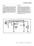
4 OPERATION Figure 1 shows the main elements of the serial timekeeper: shift register, control logic, oscillator, real-time clock, and RAM. TYPICAL OPERATING CIRCUIT DS1302 CPU VCC V CC2 SCLK CE GND X2 X1 VCC I/O V CC1 2 of 13 DS1302 Trickle-Charge Timekeeping Chip Figure 1. Block Diagram TYPICAL OPERATING CHARACTERISTICS (VCC = , TA = +25 C, unless otherwise noted.) 3 of 13 DS1302 Trickle-Charge Timekeeping Chip PIN DESCRIPTION PIN NAME FUNCTION 1 VCC2 Primary Power-Supply Pin in Dual Supply Configuration. VCC1 is connected to a backup source to maintain the time and date in the absence of primary power. The DS1302 operates from the larger of VCC1 or VCC2. When VCC2 is greater than VCC1 + , VCC2 powers the DS1302 . When VCC2 is less than VCC1, VCC1 powers the DS1302 .
5 2 X1 Connections for Standard Quartz Crystal. The internal oscillator is designed for operation with a crystal having a specified load capacitance of 6pF. For more information on crystal selection and crystal layout considerations, refer to Application Note 58: Crystal Considerations for Dallas Real-Time Clocks. The DS1302 can also be driven by an external oscillator. In this configuration, the X1 pin is connected to the external oscillator signal and the X2 pin is floated. 3 X2 4 GND Ground 5 CE Input. CE signal must be asserted high during a read or a write. This pin has an internal 40k (typ) pulldown resistor to ground. Note: Previous data sheet revisions referred to CE as RST. The functionality of the pin has not changed. 6 I/O Input/Push-Pull Output. The I/O pin is the bidirectional data pin for the 3-wire interface.
6 This pin has an internal 40k (typ) pulldown resistor to ground. 7 SCLK Input. SCLK is used to synchronize data movement on the serial interface. This pin has an internal 40k (typ) pulldown resistor to ground. 8 VCC1 Low-Power Operation in Single Supply and battery -Operated Systems and Low-Power battery Backup. In systems using the trickle charger, the rechargeable energy source is connected to this pin. UL recognized to ensure against reverse charging current when used with a lithium battery . Go to 4 of 13 DS1302 Trickle-Charge Timekeeping Chip OSCILLATOR CIRCUIT The DS1302 uses an external crystal. The oscillator circuit does not require any external resistors or capacitors to operate. Table 1 specifies several crystal parameters for the external crystal. Figure 1 shows a functional schematic of the oscillator circuit.
7 If using a crystal with the specified characteristics, the startup time is usually less than one second. CLOCK ACCURACY The accuracy of the clock is dependent upon the accuracy of the crystal and the accuracy of the match between the capacitive load of the oscillator circuit and the capacitive load for which the crystal was trimmed. Additional error will be added by crystal frequency drift caused by temperature shifts. External circuit noise coupled into the oscillator circuit may result in the clock running fast. Figure 2 shows a typical PC board layout for isolating the crystal and oscillator from noise. Refer to Application Note 58: Crystal Considerations for Dallas Real-Time Clocks for detailed information. Table 1. Crystal Specifications* PARAMETER SYMBOL MIN TYP MAX UNITS Nominal Frequency fO kHz Series Resistance ESR 45 k Load Capacitance CL 6 pF *The crystal, traces, and crystal input pins should be isolated from RF generating signals.
8 Refer to Application Note 58: Crystal Considerations for Dallas Real-Time Clocks for additional specifications. Figure 2. Typical PC Board Layout for Crystal COMMAND BYTE Figure 3 shows the command byte. A command byte initiates each data transfer. The MSB (bit 7) must be a logic 1. If it is 0, writes to the DS1302 will be disabled. Bit 6 specifies clock/calendar data if logic 0 or RAM data if logic 1. Bits 1 to 5 specify the designated registers to be input or output, and the LSB (bit 0) specifies a write operation (input) if logic 0 or read operation (output) if logic 1. The command byte is always input starting with the LSB (bit 0). Figure 3. Address/Command Byte LOCAL GROUND PLANE (LAYER 2) CRYSTAL X1 X2 GND NOTE: AVOID ROUTING SIGNALS IN THE CROSSHATCHED AREA (UPPER LEFT-HAND QUADRANT) OF THE PACKAGE UNLESS THERE IS A GROUND PLANE BETWEEN THE SIGNAL LINE AND THE PACKAGE.
9 1 RAMCKA4A3A2A1A0 RDWR76543210 5 of 13 DS1302 Trickle-Charge Timekeeping Chip CE AND CLOCK CONTROL Driving the CE input high initiates all data transfers. The CE input serves two functions. First, CE turns on the control logic that allows access to the shift register for the address/command sequence. Second, the CE signal provides a method of terminating either single-byte or multiple-byte CE data transfer. A clock cycle is a sequence of a rising edge followed by a falling edge. For data inputs, data must be valid during the rising edge of the clock and data bits are output on the falling edge of clock. If the CE input is low, all data transfer terminates and the I/O pin goes to a high-impedance state. Figure 4 shows data transfer. At power-up, CE must be a logic 0 until VCC > Also, SCLK must be at a logic 0 when CE is driven to a logic 1 state.
10 DATA INPUT Following the eight SCLK cycles that input a write command byte, a data byte is input on the rising edge of the next eight SCLK cycles. Additional SCLK cycles are ignored should they inadvertently occur. Data is input starting with bit 0. DATA OUTPUT Following the eight SCLK cycles that input a read command byte, a data byte is output on the falling edge of the next eight SCLK cycles. Note that the first data bit to be transmitted occurs on the first falling edge after the last bit of the command byte is written. Additional SCLK cycles retransmit the data bytes should they inadvertently occur so long as CE remains high. This operation permits continuous burst mode read capability. Also, the I/O pin is tri-stated upon each rising edge of SCLK. Data is output starting with bit 0. BURST MODE Burst mode can be specified for either the clock/calendar or the RAM registers by addressing location 31 decimal (address/command bits 1 through 5 = logic 1).