Transcription of DS2502 1Kb Add-Only Memory - Maxim Integrated
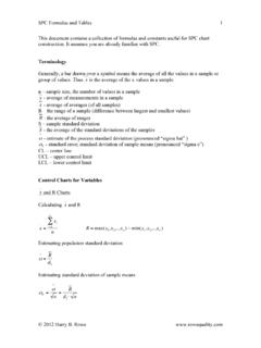
1 DS2502 . 1Kb Add-Only Memory BENEFITS AND FEATURES PIN ASSIGNMENT. Easily Add Traceability and Relevant Information to Any TO-92 NC 1 8 NC. Individual System o 1k-Bit EPROM with Page-Level Write Protection DS2502 NC 2 7 NC. and Guaranteed Unique 64-Bit ROM ID Chip for DATA 3 6 NC. Absolute Traceability GND 4 5 NC. o 1024 Bits Electrically Programmable Read Only Memory (EPROM). o Unique, Factory-Lasered and Tested 8-PIN SO (150 MIL). 64-Bit Registration Number (8-Bit Family Code + TSOC PACKAGE. 48-Bit Serial Number + 8-Bit CRC Tester). o EPROM Partitioned into Four 256-Bit Pages for GND 1 6 NC. Randomly Accessing Packetized Data DATA 2 5 NC. o Each Memory Page Can Be Permanently Write- NC 3 4 NC.
2 Protected to Prevent Tampering TOP VIEW. o Device is an Add Only Memory Where Additional NC. GND. DATA. Data Can Be Programmed into EPROM Without SOT-23 Package Disturbing Existing Data Top View o Architecture Allows Software to Patch Data by 3. Superseding an Old Page in Favor of a Newly Programmed Page 09rr o 8-Bit Family Code Specifies DS2502 1 2 3. Communications Requirements to Reader 1 2. Minimalist 1-Wire Interface Lowers Cost and Interface 1 = DATA; 2, 3 = GND. Complexity BOTTOM VIEW rr = Revision o Reduces control , Address, Data, Power, and Programming Signals to a Single Data Pin A WLP, Top View with o Directly Connects to a Single Port Pin of a Laser Mark, Contacts Microprocessor and Communicates at up to +09rrd Not Visible.
3 B rrd = Revision/Date Per Second 1A, 1B = DATA. o Built-In Multidrop Controller Ensures 1 2 2A, 2B = GND. Compatibility with Other 1-Wire Net Products o Presence Pulse Acknowledges When the Reader 1 2. First Applies Voltage SFN PINOUT: o Low Cost TO-92, SFN, or 8-Pin SO, SOT-23 (3 PIN 1: IO. Pin), TSOC and WLP Surface Mount Package PIN 2: GND. Wide Voltage and Temperature Operating Ranges Provide Robust System Performance o Reads Over Voltage Range of to at - BOTTOM VIEW SIDE VIEW. 40 C to +85 C SFN (APPROX. x x ). o Zero Standby Power Required NOTE: THE SFN PACKAGE IS QUALIFIED FOR ELECTRO-MECHANICAL. o Programs at to from -40 C CONTACT APPLICATIONS ONLY, NOT FOR SOLDERING. FOR MORE. INFORMATION, REFER TO APPLICATION NOTE 4132: ATTACHMENT.
4 To +50 C METHODS FOR THE ELECTRO-MECHANICAL SFN PACKAGE. 19-5075; Rev 3/15. 1 of 24. DS2502 . ORDERING INFORMATION. PART TEMP RANGE PIN-PACKAGE. DS2502 + -40 C to +85 C 3 TO-92 (straight leads). DS2502 +T&R -40 C to +85 C 3 TO-92 (formed leads, 2k pieces). DS2502G+T&R -40 C to +85 C 2 SFN ( pieces). DS2502P+ -40 C to +85 C 6 TSOC. DS2502P+T&R -40 C to +85 C 6 TSOC (4k pieces). DS2502R+T&R -40 C to +85 C 3 SOT-23 (3k pieces). DS2502S+ -40 C to +85 C 8 SO. DS2502S+T&R -40 C to +85 C 8 SO ( pieces). DS2502X1+ -40 C to +85 C 4 WLP (10k pieces). +Denotes a lead(Pb)-free/RoHS-compliant package. T&R = Tape and reel. DESCRIPTION. The DS2502 1Kb Add-Only Memory identifies and stores relevant information about the product to which it is associated.
5 This lot- or product-specific information can be accessed with minimal interface- for example, a single port pin of a microcontroller. The DS2502 consists of a factory-lasered registration number that includes a unique 48-bit serial number, an 8-bit CRC, and an 8-bit Family Code (09h) plus 1Kb of EPROM which is user-programmable. The power to program and read the DS2502 is derived entirely from the 1-Wire communication line. Data is transferred serially via the 1-Wire protocol which requires only a single data lead and a ground return. The entire device can be programmed and then write-protected if desired. Alternatively, the part may be programmed multiple times with new data being appended to, but not overwriting, existing data with each subsequent programming of the device.
6 Note: Individual bits can be changed only from a logical 1 to a logical 0, never from a logical 0 to a logical 1. A provision is also included for indicating that a certain page or pages of data are no longer valid and have been replaced with new or updated data that is now residing at an alternate page address. This page address redirection allows software to patch data and enhance the flexibility of the device as a stand-alone database. The 48-bit serial number that is factory-lasered into each DS2502 provides a guaranteed unique identity which allows for absolute traceability. The familiar TO-92 or SOIC or TSOC packages provide a compact enclosure that allows standard assembly equipment to handle the device easily for attachment to printed circuit boards or wiring.
7 Typical applications include storage of calibration constants, maintenance records, asset tracking, product revision status, and access codes. OVERVIEW. The block diagram in Figure 1 shows the relationships between the major control and Memory sections of the DS2502 . The DS2502 has three main data components: 1) 64-bit lasered ROM, 2) 1024-bit EPROM, and 3) EPROM Status Bytes. The device derives its power for read operations entirely from the 1-Wire communication line by storing energy on an internal capacitor during periods of time when the signal line is high and continues to operate off of this parasite power source during the low times of the 1-Wire line until it returns high to replenish the parasite (capacitor) supply.
8 During programming, 1-Wire communication occurs at normal voltage levels and then is pulsed momentarily to the programming voltage to cause the selected EPROM bits to be programmed. The 1-Wire line must be able to provide 12. volts and 10 milliamperes to adequately program the EPROM portions of the part. Whenever programming voltages are present on the 1-Wire line a special high voltage detect circuit within the DS2502 generates an internal logic signal to indicate this condition. The hierarchical structure of the 1- Wire protocol is shown in Figure 2. The bus master must first provide one of the six ROM Function Commands, 1) Read ROM, 2) Match ROM, 3) Search ROM, 4) Skip ROM. These commands operate on the 64-bit lasered ROM portion of each device and can singulate a specific device if many are present on 1-Wire is a registered trademark of Maxim Integrated Products, Inc.
9 2 of 24. DS2502 . the 1-Wire line as well as indicate to the bus master how many and what types of devices are present. The protocol required for these ROM Function Commands is described in Figure 9. After a ROM Function Command is successfully executed, the Memory functions that operate on the EPROM portions of the DS2502 become accessible and the bus master may issue any one of the five Memory Function Commands specific to the DS2502 to read or program the various data fields. The protocol for these Memory Function Commands is described in Figure 5. All data is read and written least significant bit first. 64-BIT LASERED ROM. Each DS2502 contains a unique ROM code that is 64 bits long. The first 8 bits are a 1-Wire family code.
10 The next 48 bits are a unique serial number. The last 8 bits are a CRC of the first 56 bits. (See Figure 3). The 64-bit ROM and ROM Function control section allow the DS2502 to operate as a 1-Wire device and follow the 1-Wire protocol detailed in the section 1-Wire Bus System. The Memory functions required to read and program the EPROM sections of the DS2502 are not accessible until the ROM function protocol has been satisfied. This protocol is described in the ROM functions flow chart (Figure 9). The 1- Wire bus master must first provide one of four ROM function commands: 1) Read ROM, 2) Match ROM, 3) Search ROM, or 4) Skip ROM. After a ROM function sequence has been successfully executed, the bus master may then provide any one of the Memory function commands specific to the DS2502 (Figure 6).