Transcription of EARTHING - IIT Bombay
1 EARTHING18 IEE Wiring Matters |Autumn 2005 | article, which is based on IEE Guidance notes, isintended to provide information that it is hoped willprove 7671 lists five types of EARTHING system: TN-S, TN-C-S, TT, TN-C, and IT. T =Earth (from the French word Terre) N =Neutral S =Separate C =CombinedI =Isolated (The source of an IT system is eitherconnected to earth through a deliberately introducedearthing impedance or is isolated from Earth. Allexposed-conductive-parts of an installation areconnected to an earth electrode.)
2 When designing an electrical installation, one ofthe first things to determine is the type of earthingsystem. The distributor will be able to provide system will either be TN-S, TN-C-S (PME) or TTfor a low voltage supply given in accordance with theElectricity Safety, Quality and Continuity Regulations2002. This is because TN-C requires an exemptionfrom the Electricity Safety, Quality and ContinuityRegulations, and an IT system is not permitted for alow voltage public supply in the UK because thesource is not directly earthed.
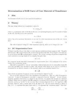
3 Therefore TN-C and ITsystems are both very uncommon in the :YOUR QUESTIONS ANSWEREDBy Geoff CronshawWhat are earthed and unearthed systems? What are the requirements of BS 7671? What are the advantages and disadvantages of the various types of EARTHING systems?EARTHINGIEE Wiring Matters |Autumn 2005 | Overview of EARTHING TN-S system earthingA TN-S system, shown in fig 1, has the neutral of the source of energyconnected with earth at one point only, at or as near as is reasonablypracticable to the source, and the consumer s EARTHING terminal is typicallyconnected to the metallic sheath or armour of the distributor s service cableinto the >MG&L lrlm^f>qihl^]&\hg]
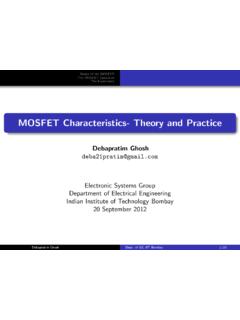
4 N\mbo^&iZkmLhnk\^ h_ lniierLhnk\^ >ZkmaBglmZeeZmbhgG&LBglmZeeZmbhg>jnbif^g mGEGEMAINEARTHINGTERMINALELECTRICITYCOMP ANYISOLATOR !Fig 2:Cable sheath earth(TN-S system). Schematic ofearthing and mainequipotential bondingarrangements. Based on 25 mm2tails and selectionfrom Table 54G. Note: An isolator is notalways installed by theelectricity 1:TN-S systemEARTHING20 IEE Wiring Matters |Autumn 2005 | TN-C-S system earthingA TN-C-S system, shown in fig 3, has the supplyneutral conductor of a distribution main connectedwith earth at source and at intervals along its is usually referred to as protective multipleearthing (PME).
5 With this arrangement thedistributor s neutral conductor is also used to returnearth fault currents arising in the consumer sinstallation safely to the source. To achieve this, thedistributor will provide a consumer s earthingterminal which is linked to the incoming >GGI>Lhnk\^ >Zkma:]]bmbhgZeLhnk\^ >e^\mkh]^!\hf[bg^] g^nmkZe Zg]ikhm^\mbo^ \hg]n\mhk !I>G"bg lhnk\^ h_ lniier%pbma IF> Ziieb^]"!l^iZkZm^ g^nmkZe !G" Zg]ikhm^\mbo^ \hg]n\mhkl!I>"pbmabg bglmZeeZmbhg"EbgdG&<LBglmZeeZmbhg>jnbif^gm*)) :Fig 3:TN-C-S systemFig 4:PME supply (TN-C-Ssystem).
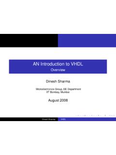
6 Schematic of earthingand main equipotential bondingarrangements. Based on 25 mm2tails and selection from Table : An isolator is not alwaysinstalled by the Wiring Matters |Autumn 2005 | Requirements of BS 7671 Earth electrodesBS 7671 recognises a wide variety of types of earthelectrode. Regulation 542-02-01 lists the typesrecognised which include earth rods, earth plates and*)):Figure 5:TT systemFigure 6:No earth provided(TT system). Based on 25 mm2tails and selectionfrom Table 54G. Note: An isolator is notalways installed by theelectricity shouldbe sought with regards toconnections to \^ >Zkma<hglnf^k l >ZkmaMMBglmZeeZmbhg>jnbif^gmMM lrlm^ TT system earthingA TT system, shown above, has the neutral of the source ofenergy connected as for TN-S, but no facility is provided by thedistributor for the consumer s EARTHING .
7 With TT, theconsumer must provide their own connection to earth, byinstalling a suitable earth electrode local to the installation. EARTHING22 IEE Wiring Matters |Autumn 2005 | structural metal work. The soil resistivity of the ground is probably thesingle most important factor in the determination ofthe type of earth electrode. Rods can only be aseffective as the contact they make with thesurrounding material. Thus, they should be driveninto virgin ground, not disturbed (backfilled) it is necessary to drive two or more rods andconnect them together to achieve a satisfactory result,the separation between rods should be at least equalto their combined driven depth to obtain maximumadvantage from each rod.
8 In some locations low soilresistivity is found to be concentrated in the topsoillayer, beneath which there may be rock or otherimpervious strata which prevents the deep driving ofrods, or a deep layer of high resistivity. Only a test orknown information about the ground can reveal thiskind of information. In such circumstances, theinstallation of copper earth tapes, or pipes or plates,would be most likely to provide a satisfactory earthelectrode resistance form an earth electrode takes, thepossibility of soil drying and freezing, and ofcorrosion, must be taken into account.
9 Preferably,testing of an earth electrode should be carried outunder the least favourable conditions, afterprolonged dry weather. Further information onearthing principles and practice can be found in BS 7430 : 1998 Code of Practice for EARTHING . EARTHING conductorsEarthing conductors which are defined in BS 7671 as aprotective conductor connecting the main earthingterminal of an installation to an earth electrode orother means of EARTHING must be adequately sizedparticularly where buried partly in the ground, andbe of suitable material and adequately protectedagainst corrosion and mechanical damage.
10 The size of an EARTHING conductor is arrived at inbasically the same way as for a circuit protectiveconductor, except that Table 54A of BS 7671 must beapplied to any buried EARTHING conductor. For a TN-C-S (PME) supply, it should be no smaller than themain bonding of circuit protective conductorsThere are several factors which may influence ordetermine the size required for a circuit protectiveconductor. A minimum cross-sectional area mm2copper is required for any separate circuitprotective conductor, one which is not part of acable or formed by a wiring enclosure or contained insuch an enclosure.