Transcription of EE 0308 POWER SYSTEM ANALYSIS …
1 EE 0308 POWER SYSTEM ANALYSIS Professor, EEE Dept. POWER SYSTEM OVERVIEW POWER SYSTEM components, Representation. Single line diagram, per phase ANALYSIS of symmetrical three phase systems, general aspects relating to POWER flow, short circuit and stability ANALYSIS , per unit quantities, impedance diagram. POWER FLOW ANALYSIS Primitive network, Formation of Bus admittance matrix by inspection method and singular method. Bus classification Formulation of POWER Flow problems POWER flow solution using Gauss Seidel method and Newton Raphson method, Comparison between these methods. Handling of Voltage controlled buses, Off nominal transformer ratios and phase shifting transformer. SYMMETRICAL FAULT ANALYSIS Formation of Bus Impedance matrix by Z bus building algorithm.
2 Types of faults in POWER systems Symmetrical fault ANALYSIS . Short circuit capacity Symmetrical fault ANALYSIS through bus impedance matrix. UNSYMMETRICAL FAULT ANALYSIS Symmetrical components sequence impedance sequence networks, Introduction to unsymmetrical faults. Single line to ground fault, line to line and double line to ground faults Unsymmetrical fault ANALYSIS using bus impedance matrix. POWER SYSTEM STABILITY Introduction to stability studies classification of stability Transient stability Equal area criterion critical clearing angle and time Factors affecting transient stability. Numerical integration method: Euler method, Modified Euler s method, Fourth order Runge Kutta method. TEXT BOOKS 1.
3 Hadi Sadat, POWER SYSTEM ANALYSIS , Tata Mc Graw Hill Publishing company, New Delhi, 2002. 2. , William D. Stevenson, POWER SYSTEM ANALYSIS , Tata Mc Graw Hill Publishing company, New Delhi, 2003. REFERENCE BOOKS 1. Nagarath and Kothari Modern POWER SYSTEM ANALYSIS , Tata Mc Graw Hill Publishing company, New Delhi, 2002. 2. Wadhwa Electrical POWER Systems, New age international (P) Ltd. Publishers, 1995. 3. Pai Computer Techniques in POWER SYSTEM ANALYSIS , Tata Mc Graw Hill Publishing company, New Delhi, 2003. EE 0308 POWER SYSTEM ANALYSIS Chapter 1 POWER SYSTEM OVERVIEW Introduction A POWER SYSTEM consists of a few generating plants, situated close to resources, supplying electric POWER to various types of loads spread out over large area, through large complex transmission and distribution network.
4 Thus a POWER SYSTEM compose of 1. Generation SYSTEM 2. Transmission SYSTEM 3. Distribution SYSTEM 4. Loads Depending on the fuel used we have Hydro-Electric POWER Plants, Thermal POWER Plants and Nuclear POWER Plants. Generated supply will be of 11 kV. To have greater efficiency, transmission is carried out at high voltages of order 230 kV or 400 kV. POWER transformers are used to setup the voltage levels. Transmission SYSTEM consists of transformers, transmission towers and transmission lines. Thereafter, voltage levels are reduced in stages. Distribution SYSTEM supplies POWER to different loads. Thus POWER SYSTEM network is large, complex and very expensive. POWER SYSTEM ANALYSIS deals with ANALYSIS problems associated with POWER network.
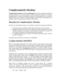
5 POWER Flow ANALYSIS , Short Circuit ANALYSIS and Transient Stability Study are the main POWER SYSTEM ANALYSIS Problems. CE CI AI BI BE Z n AE 0 Z Z Single line diagram or One-line diagram Electric POWER systems are supplied by three-phase generators. Ideally, the generators are supplying balanced three phase loads. shows a star connected generator supplying star connected balanced load. Fig. Y- connected generator supplying balanced Y- connected load Z n AE 0 AI A balanced three-phase SYSTEM is always solved as a single-phase circuit composed of one of the three lines and the neutral return. Single-phase circuit of three-phase SYSTEM considered above is shown in Fig. Often the diagram is simplified further by omitting the neutral and by indicating the component parts by standard symbols rather than by their equivalent circuits.
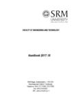
6 Such a simplified diagram of electric SYSTEM is called a one-line diagram. It is also called as single line diagram. The one-line diagram of the simple three-phase SYSTEM considered above is shown in Fig. Fig. Single-phase circuit Z n AE 0 AI Fig. shows the one-line diagram of a sample POWER SYSTEM . Fig. One-line diagram Load Fig. Single-phase circuit Load A 2 3 1 Load B T2 T1 Fig. One-line diagram of a sample POWER SYSTEM Fig. shows the one-line diagram of a sample POWER SYSTEM . This SYSTEM has two generators, one solidly grounded and the other grounded through a resistor, that are connected to a bus and through a step-up transformer to a transmission line. Another generator, grounded through a reactor, is connected to a bus and through a transformer to the other end of the transmission line.
7 A load is connected to each bus. On the one-line diagram information about the loads, the ratings of the generators and transformers, and reactances of different components of the circuit is often given. Per phase ANALYSIS of symmetrical three phase systems Per phase ANALYSIS of symmetrical three phase systems are illustrated through the following three examples. Load A 2 3 1 Load B T2 T1 Fig. One-line diagram of a sample POWER SYSTEM EXAMPLE A balanced three-phase load connected in star consists of (6+8) impedance in each phase. It is connected to a three phase supply of 400 V, 50 Hz. Find (i) Phase current (ii) Line current (iii) Per phase POWER and (iV) Total POWER SOLUTION Fig. Balanced three phase load 1 phase equivalent Three phase star connected balanced load and the corresponding single phase equivalent are shown in Fig.
8 (a) and (b) EXAMPLE Repeat the previous problem with the load impedance connected in delta. SOLUTION Fig. Balanced three phase load 1 phase equivalent Three phase delta connected balanced load and the corresponding single phase equivalent are shown in Fig. (a) and (b). V240-1100 V120-1100 C V01100 A B - + + + - - EXAMPLE Calculate the line currents in the three wire Y-Y SYSTEM of Fig. ( +j4) ( +j4) Fig. Three wire SYSTEM for Example ( +j6) ( +j6) ( +j6) ( +j4) V01100 A + - SOLUTION The single phase equivalent of the given three phase SYSTEM is shown in Fig. Total impedance = ( 4 + j10) Current )(40110I00A Since the source voltages are in positive sequence, the line currents are also in positive sequence.
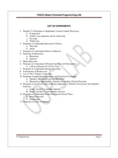
9 Therefore ; ( +j4) Fig. Single phase equivalent ( +j6) Impedance and reactance diagram In order to calculate the performance of a POWER SYSTEM under load condition or upon the occurrence of a fault, the one line diagram is used to draw the single-phase or per phase equivalent circuit of the SYSTEM . Refer the one-line diagram of a sample POWER SYSTEM shown in Fig. combines the equivalent circuits for the various components shown in Fig. to form the per-phase impedance diagram of the SYSTEM . Load A 2 3 1 Load B T2 T1 Fig. One-line diagram of a sample POWER SYSTEM combines the equivalent circuits for the various components shown in Fig. to form the per-phase impedance diagram of the SYSTEM The impedance diagram does not include the current limiting impedances shown in the one-line diagram because no current flows in the ground under balanced condition.
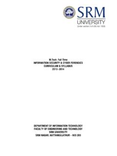
10 Fig. Per-phase impedance diagram Load A 2 3 1 Load B T2 T1 Fig. One-line diagram of a sample POWER SYSTEM + - E3 E1 - + E2 - + Fig. Per-phase impedance diagram Fig. Per-phase reactance diagram Per-unit quantities Absolute values may not give the full significance of quantities. Consider the marks scored by a student in three subjects as 10, 40 and 95. Many of you may be tempted to say that he is poor in subject 1, average in subject 2 and good in subject 3. That is true only when the base for all the marks is 100. If the bases are 10, 50 and 100 for the three subjects respectively then his marks in percentage are 100,80 and 95 and thus the conclusions are different.