Transcription of EE101: Diode circuits
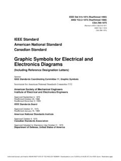
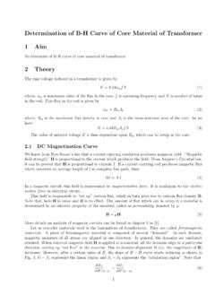
1 EE101: Diode circuits M. B. Patil ~sequel Department of Electrical Engineering Indian Institute of Technology Bombay M. B. Patil, IIT Bombay Diodes i flow V pressure M. B. Patil, IIT Bombay Diodes i flow V pressure * A Diode may be thought of as an electrical counterpart of a directional valve ( check valve ). M. B. Patil, IIT Bombay Diodes i flow V pressure * A Diode may be thought of as an electrical counterpart of a directional valve ( check valve ). * A check valve presents a small resistance if the pressure p > 0, but blocks the flow ( , presents a large resistance) if p < 0. M. B. Patil, IIT Bombay Diodes i flow V pressure * A Diode may be thought of as an electrical counterpart of a directional valve ( check valve ). * A check valve presents a small resistance if the pressure p > 0, but blocks the flow ( , presents a large resistance) if p < 0. * Similarly, a Diode presents a small resistance in the forward direction and a large resistance in the reverse direction.
2 M. B. Patil, IIT Bombay Diodes i flow V pressure * A Diode may be thought of as an electrical counterpart of a directional valve ( check valve ). * A check valve presents a small resistance if the pressure p > 0, but blocks the flow ( , presents a large resistance) if p < 0. * Similarly, a Diode presents a small resistance in the forward direction and a large resistance in the reverse direction. * In the forward direction, the Diode resistance RD = V /i would be a function of V . However, it is often a good approximation to treat it as a constant (small). resistance. M. B. Patil, IIT Bombay Diodes i flow V pressure * A Diode may be thought of as an electrical counterpart of a directional valve ( check valve ). * A check valve presents a small resistance if the pressure p > 0, but blocks the flow ( , presents a large resistance) if p < 0. * Similarly, a Diode presents a small resistance in the forward direction and a large resistance in the reverse direction.
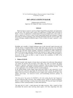
3 * In the forward direction, the Diode resistance RD = V /i would be a function of V . However, it is often a good approximation to treat it as a constant (small). resistance. * In the reverse direction, the Diode resistance is much larger and may often be treated as infinite ( , the Diode may be replaced by an open circuit). M. B. Patil, IIT Bombay Simple models: Ron /Roff model i i R = Ron if V > 0. R = Roff if V < 0. V V. M. B. Patil, IIT Bombay Simple models: Ron /Roff model i i R = Ron if V > 0. R = Roff if V < 0. V V. * Since the resistance is different in the forward and reverse directions, the i V. relationship is not symmetric. M. B. Patil, IIT Bombay Simple models: Ron /Roff model i i R = Ron if V > 0. R = Roff if V < 0. V V. * Since the resistance is different in the forward and reverse directions, the i V. relationship is not symmetric. * Examples: M. B. Patil, IIT Bombay Simple models: Ron /Roff model i i R = Ron if V > 0.
4 R = Roff if V < 0. V V. * Since the resistance is different in the forward and reverse directions, the i V. relationship is not symmetric. * Examples: 10. Ron = 5 Ron = . Roff = 500 Roff = 1 M . i (mA). 0. 5 4 3 2 1 0 1 5 4 3 2 1 0 1. V (Volts) V (Volts). M. B. Patil, IIT Bombay Simple models: ideal switch i i i i S S closed, V > 0. i S open, V < 0. V V V V. M. B. Patil, IIT Bombay Simple models: ideal switch i i i i S S closed, V > 0. i S open, V < 0. V V V V. * V > 0 Volts S is closed (a perfect contact), and it can ideally carry any amount of current. The voltage drop across the Diode is 0 V . M. B. Patil, IIT Bombay Simple models: ideal switch i i i i S S closed, V > 0. i S open, V < 0. V V V V. * V > 0 Volts S is closed (a perfect contact), and it can ideally carry any amount of current. The voltage drop across the Diode is 0 V . * V < 0 Volts S is open (a perfect open circuit), and it can ideally block any reverse voltage.
5 The current through the Diode is 0 A. M. B. Patil, IIT Bombay Simple models: ideal switch i i i i S S closed, V > 0. i S open, V < 0. V V V V. * V > 0 Volts S is closed (a perfect contact), and it can ideally carry any amount of current. The voltage drop across the Diode is 0 V . * V < 0 Volts S is open (a perfect open circuit), and it can ideally block any reverse voltage. The current through the Diode is 0 A. * The actual values of V and i for a Diode in a circuit get determined by the i-V. relationship of the Diode and the constraints on V and i imposed by the circuit. M. B. Patil, IIT Bombay Shockley Diode equation i i p n V V. M. B. Patil, IIT Bombay Shockley Diode equation . V. i = Is exp 1 , where VT = kB T /q . VT. i i kB = Boltzmann's constant = 10 23 J/K . p n q = electron charge = 10 19 Coul. V V. T = temperature in K . VT 25 mV at room temperature (27 C).
6 M. B. Patil, IIT Bombay Shockley Diode equation . V. i = Is exp 1 , where VT = kB T /q . VT. i i kB = Boltzmann's constant = 10 23 J/K . p n q = electron charge = 10 19 Coul. V V. T = temperature in K . VT 25 mV at room temperature (27 C). * Is is called the reverse saturation current.. M. B. Patil, IIT Bombay Shockley Diode equation . V. i = Is exp 1 , where VT = kB T /q . VT. i i kB = Boltzmann's constant = 10 23 J/K . p n q = electron charge = 10 19 Coul. V V. T = temperature in K . VT 25 mV at room temperature (27 C). * Is is called the reverse saturation current.. * For a typical low-power silicon Diode , Is is of the order of 10 13 A. M. B. Patil, IIT Bombay Shockley Diode equation . V. i = Is exp 1 , where VT = kB T /q . VT. i i kB = Boltzmann's constant = 10 23 J/K . p n q = electron charge = 10 19 Coul. V V. T = temperature in K . VT 25 mV at room temperature (27 C).
7 * Is is called the reverse saturation current.. * For a typical low-power silicon Diode , Is is of the order of 10 13 A. * Although Is is very small, it gets multiplied by a large exponential factor, giving a Diode current of several mA for V V . M. B. Patil, IIT Bombay Shockley Diode equation . V. i = Is exp 1 , where VT = kB T /q . VT. i i kB = Boltzmann's constant = 10 23 J/K . p n q = electron charge = 10 19 Coul. V V. T = temperature in K . VT 25 mV at room temperature (27 C). * Is is called the reverse saturation current.. * For a typical low-power silicon Diode , Is is of the order of 10 13 A. * Although Is is very small, it gets multiplied by a large exponential factor, giving a Diode current of several mA for V V . * The turn-on voltage (Von ) of a Diode depends on the value of Is . Von may be defined as the voltage at which the Diode starts carrying a substantial forward current (say, a few mA).
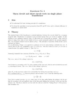
8 For a silicon Diode , Von V . For a GaAs Diode , Von V . M. B. Patil, IIT Bombay Shockley Diode equation . i V. i i = Is exp 1 , where VT = kB T /q . p n VT. V V. Example: Is = 1 10 13 A, VT = 25 mV . M. B. Patil, IIT Bombay Shockley Diode equation . i V. i i = Is exp 1 , where VT = kB T /q . p n VT. V V. Example: Is = 1 10 13 A, VT = 25 mV . V x = V /VT ex i (Amp). 102 10 11. 104 10 9. 106 10 7. 107 10 6. 109 10 4. 1011 10 2. 1011 10 2. 1011 10 2. 1012 10 1. 1012 10 1. 1012 10 1. 1013 M. B. Patil, IIT Bombay Shockley Diode equation . i V. i i = Is exp 1 , where VT = kB T /q . p n VT. V V. Example: Is = 1 10 13 A, VT = 25 mV . V x = V /VT ex i (Amp). 102. 1. 10 11 log scale 104 10 9. i (Amp). 106 10 7 10 6. 107 10 6. 109 10 4. 10 12. 1011 10 2 100. linear scale 1011 10 2 80. 1011 10 2. i (mA). 60. 1012 10 1 40. 1012 10 1 20. 1012 10 1 0. 0 V (Volts). 1013 M. B. Patil, IIT Bombay Shockley equation and simple models i i h i p n i = Is eV/VT 1 , Is = 10 13 A , VT = 25 mV.
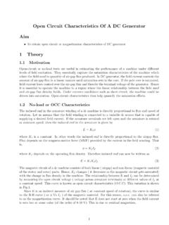
9 V V. Shockley equation and simple models i i h i p n i = Is eV/VT 1 , Is = 10 13 A , VT = 25 mV . V V. 100. Model 1: Von 80 i V > Von 60 V < Von i (mA). (open circuit). 40 Shockley equation 20. Von = V Model 1. 0. 0 V (Volts) Von Shockley equation and simple models i i h i p n i = Is eV/VT 1 , Is = 10 13 A , VT = 25 mV . V V. 100. Model 1: Model 2: Von Von Ron 80 i i V > Von V > Von 60 V < Von V < Von i (mA). (open circuit) (open circuit). 40 Shockley equation Shockley slope = 1/Ron 20 Von = V equation Von = V Model 1. Ron = Model 2. 0. 0 0 V (Volts) Von V (Volts) Von M. B. Patil, IIT Bombay Shockley equation and simple models i i h i p n i = Is eV/VT 1 , Is = 10 13 A , VT = 25 mV . V V. 100. Model 1: Model 2: Von Von Ron 80 i i V > Von V > Von 60 V < Von V < Von i (mA). (open circuit) (open circuit). 40 Shockley equation Shockley slope = 1/Ron 20 Von = V equation Von = V Model 1.
10 Ron = Model 2. 0. 0 0 V (Volts) Von V (Volts) Von * For many circuits , Model 1 is adequate since Ron is much smaller than other resistances in the circuit. M. B. Patil, IIT Bombay Shockley equation and simple models i i h i p n i = Is eV/VT 1 , Is = 10 13 A , VT = 25 mV . V V. 100. Model 1: Model 2: Von Von Ron 80 i i V > Von V > Von 60 V < Von V < Von i (mA). (open circuit) (open circuit). 40 Shockley equation Shockley slope = 1/Ron 20 Von = V equation Von = V Model 1. Ron = Model 2. 0. 0 0 V (Volts) Von V (Volts) Von * For many circuits , Model 1 is adequate since Ron is much smaller than other resistances in the circuit. * If Von is much smaller than other relevant voltages in the circuit, we can use Von 0 V , and the Diode model reduces to the ideal Diode model seen earlier. M. B. Patil, IIT Bombay Shockley equation and simple models i i h i p n i = Is eV/VT 1 , Is = 10 13 A , VT = 25 mV.