Transcription of Electrical Distribution Equipment in Data Center …
1 Electrical Distribution Equipment in data Center Environments Revision 1 by Pearl Hu White Paper 61 IT professionals who are not familiar with the concepts, terminology, and Equipment used in Electrical distribu-tion, can benefit from understanding the names and purposes of Equipment that support the data Center , as well as the rest of the building in which the data Center is located. This paper explains Electrical distri-bution terms and Equipment types and is intended to provide IT professionals with useful vocabulary and frame of reference.
2 Executive summary by schneider electric White Papers are now part of the schneider electric white paper library produced by schneider electric s data Center Science Center Electrical Distribution Equipment in data Center Environments schneider electric data Center Science Center Rev 1 2 Electrical Distribution systems are designed to power Equipment in a safe and reliable manner. While many power Distribution systems may, on the surface, appear very similar, there are specific attributes that distinguish them from each other. For IT professionals, the terminology can be very confusing high voltage, medium voltage, low voltage; switchgear, switchboards, panel boards, power Distribution units, etc.
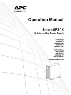
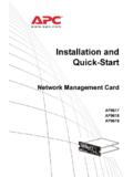
3 This paper defines these key terms, and provides an overview of the functions, placement, and standards for key Electrical Distribution Equipment in data centers. Detailed Equipment selection and design is not covered in this white paper. Figure 1 provides a block diagram of an Electrical Distribution system showing the name and the typical location of the Electrical Distribution Equipment in a data Center and the power flow path. This diagram is only an example of an Electrical architecture and attempts to include all the possible major types of Equipment used and their typical location in a data Center . In the real world, a typical data Center Electrical design has much more complexity and diversity than that in Figure 1.
4 Some of the common variants are summarized in the Summary of Electrical Equipment section. Note that Electrical designs are typically expressed as single-line diagrams (see side bar). Medium-voltage switchgearLow-voltage switchgearUPSUPS output switchboardUPSUPS output switchboardLV GenLV switchgearLightingPDUPDUSTSPDUD ouble-cordedIT devicesSingle-cordedIT devicesCooling Panelboard for lightingRPPRPPRPPMV/LVtransformerUPS Distribution switchboardrPDUrPDUrPDURackRackUtilityPa nelboard for coolingIT SpaceElectrical SpaceMechanical SpaceCooling data CenterCooling UnitIT devicesRackPanelboard for coolingUPS Distribution switchboardrPDUB usway Introduction Figure 1 Block diagram showing an Electrical Distribution system in a data Center Single-line vs.
5 5-line Drawings or schematics that describe a data Center s Electrical design are usually referred to as single-line diagrams because all the wires ( 3-phases, neutral, and ground) are represented by a single line connecting all the major components such as circuit breakers and transform-ers. However, when there is a need for more detailed drawings that show the connections for all phase, neutral, and ground wires, a 5-line drawing is used. As the name suggests, 5-line drawings show all 5 wires of an Electrical system and are useful to understand the effects of a ground fault, or circulating currents, or other anomalies that the Electrical system may experience.
6 Electrical Distribution Equipment in data Center Environments schneider electric data Center Science Center Rev 1 3 Typically the utility supplies a medium voltage (MV) service to a dedicated data Center . Then the MV is stepped down to low voltage (LV) by a MV/LV transformer located in the data Center . LV power is distributed to the different Electrical loads such as IT devices inside the racks, cooling system, lighting, etc by the Electrical Distribution Equipment shown in the blocks in Figure 1. Some small data centers are supplied from utility pad-mounted trans-formers at low voltage, while large multi-megawatt data centers can specify the operational voltage level to be high voltage (HV) or MV.
7 The type and location of the HV/MV substation can be contracted by the data Center owner and the utility. Access to high voltage Equipment including HV switchgear and HV/MV transformers is reserved for utility personnel and is not discussed further in this paper. Voltage standards are usually stated using two values such as the IEC standard 400/230V1 or the North American voltage 415/240V for high-efficiency green data centers2. However, IT professionals still have difficulty understanding what this means. What is the relationship between these two values? What s the difference between the IEC and North American voltage standard? Why is 100-240 Vac input voltage shown on the label of the servers in our data Center ?
8 To better understand data Center Electrical dist ribution voltages, it is helpful to learn about the Electrical Distribution Equipment itself. Three-phase system vs. single-phase system The Electrical Distribution in data centers is typically an alternating current (AC) three-phase system. The term AC three-phase system means that AC three-phase voltage is provided by each of the three separate coils of a transformer. The term single-phase system means that single-phase voltage is provided by a single transformer coil. Transformers found in data centers are typically three-phase (three separate coils) and step down from a higher input voltage (also known as primary voltage) to a lower output voltage (also known as secondary voltage).
9 The terms 3-wire and 4-wire are often used to describe the Electrical system design. The term 3-wire means that there are three hot conductors, line 1, 2, and 3 shown in Figure 2. While the term 4-wire means that in addition to three hot conductors there is a fourth neutral conductor. The neutral is required to supply line-to -neutral voltage to most IT loads as shown in Figure 2. In addition to the wires described above, there is a final type of wire that is mandatory in all data centers called the ground wire or protective earth (PE). The purpose of the ground wire is to provide human safety against electrocution as well as protection of Electrical Equipment .
10 This is accomplished by connecting a ground wire to all exposed metal parts of all Equipment (including IT Equipment ) in the data Center . In the event of a phase to ground fault, the ground wire acts as a low resistance path for current to flow which opens the circuit breaker or fuse. In summary, there are two types of three-phase systems: 3-wire plus ground and 4-wire plus ground. In some regions, the 4-wire plus ground system is referred to as a 5-wire Electrical system. Figure 2 illustrates the different ways in which data Center loads can connect to the Electrical system. Single-phase loads, such as an IT server, are connected to one hot conductor and 1 The designation of the two values when written as 400/230 represents the line-to-line voltage (the higher value) and the line-to-neutral voltage (the lower value).