Transcription of ELECTROMAGNETIC TESTING TECHNIQUES
1 ELECTROMAGNETIC TESTING TECHNIQUES FOR QUALITY GRADING OF NONFERROUS ROD AND WIRE John Markanich, Product Engineer Foerster Instruments, Inc., Pittsburgh, PA INTRODUCTION: ELECTROMAGNETIC nondestructive inspection is widely used as a technique for grading the quality of nonferrous rod and wire. The inspection is performed without disruption to the manufacturing process. The two individual inspections of eddy current flaw detection and ferrous inclusion detection are performed with a single non-contact encircling coil. Eddy current inspection is a very sensitive technique to detect cracks, monitor the general surface condition, and detect defects occurring on or near the surface of the material. By interrogating the entire outer circumference of the rod or wire, it also provides an early indication of die wear. Ferrous inclusion inspection detects ferrous particles that become imbedded in the rod or wire during the manufacturing process.
2 This technique provides an early indication of roll wear. Early detection of ferrous inclusions helps to eliminate many of the wire breaks that occur during further size reduction processes. It is interesting to note that as the line speed increases, as is typically the case in reduction processes, the detectability of ferrous inclusions also increases. The ELECTROMAGNETIC inspection process provides a very effective method of ascertaining the product quality of non-ferrous rod and wire. The quantity and density of individual surface flaws and inclusions are continuously compared to user defined pre-established quality grading parameters. It will provide the customer with an incremental progress report and a proper technique to determine the product s overall quality. The ELECTROMAGNETIC test is also a very effective tool for process control monitoring of the manufacturing process.
3 Proper implementation of the ELECTROMAGNETIC test technique can insure decreased downtime, improve product yield, and help produce a better quality finished product. Standard features of the ELECTROMAGNETIC test include compatibility with plant software, permanent records of the test results, and documentation for each coil of rod or wire, each customer order, and each production run. COMBINATION TEST (SINGLE COIL INSPECTION): The ELECTROMAGNETIC technique performs a continuous inspection of the non-ferrous rod and wire during the actual manufacturing process. The product passes through an encircling test coil and holder apparatus without contact. Since the rod and wire do not come into physical contact with the test coil, the inspection does not interrupt or slow down production. Both ELECTROMAGNETIC inspections (eddy current inspection and ferrous inclusion detection) are performed simultaneously with the same encircling test coil.
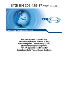
4 Since the encircling coil completely surrounds the product, the entire outer circumference of the rod or wire product is inspected. The advanced filtering capabilities for the ELECTROMAGNETIC inspection do not impose any restrictions on the speed of the manufacturing process. TESTING can take place at line speeds up to 20,000 feet per minute (100 meters per second). Figure 1 Combination Eddy Current and Ferrous Inclusion Test Coils The rod or wire is fed through the transmitter system, which consists of a single encircling coil and a magnetizing coil holder. A shielded coil cable sends the test responses to the combination eddy current and ferrous inclusion test electronics. The magnetizing coil holder has steel guides at both the inlet and outlet sides. The guides concentrate the magnetic field into the rod or wire product to magnetize the ferrous particles to provide for detection.
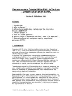
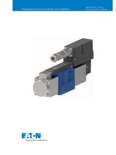
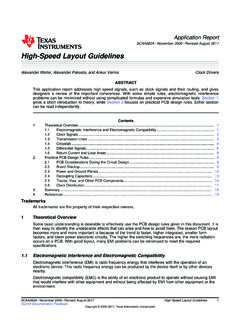
5 Magnetization is not a requirement for the eddy current inspection. The signal from the coil will be transmitted through a shielded coil cable into the ferrous inclusion detection electronics first and then into the eddy current electronics. Figure 2 Magnetizing Coil Holder with Permanent Magnets Pictured above is a magnetizing coil holder using permanent magnets to provide magnetization for the ferrous inclusion inspection. Although the permanent magnet system does not have the field strength of electromagnets, it is less expensive and less costly to operate than the electromagnet. Pictured below is an electromagnet coil holder. The electromagnet provides significantly more magnetizing field strength. The detectability of ferrous inclusions increases with increased magnetizing field strength. Figure 3 Magnetizing Coil Holder (Electromagnet) The ELECTROMAGNETIC inspection can take place in the process directly after the casting and before the cooling bed.
6 In this case, a water-cooled test coil and holder apparatus is placed inline as shown in the simple process diagram shown below. The water-cooling protects the coil windings from the excessive temperatures of the process. Figure 4 Hot TESTING Process Diagram The test coil can also be placed after the cooling system using standard ambient temperature coils. Typically in copper processing, this initial manufacturing process produces rod to a finished diameter of 5/16 ( ). A simple process diagram is shown below. The test coil is located after the cooling bed and just prior to the coiling operation. Figure 5 TESTING After Cooling Operation In the next process, non-ferrous rod may be further reduced through a first drawing operation to produce an intermediate diameter. A first pass reduction, for example, may reduce the rod size to 7/32 ( , ).
7 The purpose of the ELECTROMAGNETIC tests at this point in the process is to detect any defects and ferrous inclusions severe enough to cause a wire break during the next reduction process. If the first reduction pass is made, for example, to 7/32 ( , ), a 30% reduction from the rod size, virtually all inclusions that would cause a wire break will have been already detected. It is claimed that for reductions less than 50% of wire diameter, no inclusions capable of causing a wire break will escape detection of the ferrous inclusion test. Tests performed during one operation, therefore, will determine the success for the next drawing pass. In addition to detecting inclusions and defects in the material, the focus of the inspection is to grade the quality of the rod or wire product and determine its suitability for future sizing and end use.
8 Before elaborating on the method and TECHNIQUES used for the grading of non-ferrous rod and wire, details regarding the actual inspection TECHNIQUES will be investigated. Eddy current inspection detects stress cracks that occur during the casting process in addition to scaling and laminations that occur during the rolling process. Ferrous inclusions can be introduced during the rolling process or during the casting process if ferrous materials are inserted into the scrap. EDDY CURRENT SURFACE CONDITION AND FLAW INSPECTION: Eddy current inspection is the more traditional of the two ELECTROMAGNETIC test TECHNIQUES used for the nondestructive inspection of nonferrous rod and wire. Eddy current inspection is a very sensitive method for detecting cracks and other defects found on or near the surface of the material being inspected.
9 It is also a very effective method for monitoring the general surface condition of the rod or wire product. In eddy current inspection, an alternating electrical current is provided at a fixed frequency into a test coil s primary field windings (excitation coil). This alternating current produces an alternating magnetic field. As the rod or wire passes through this magnetic field, eddy currents are induced into the product along its circumference. These eddy currents generate a secondary magnetic field in opposition to the coil s primary magnetic field. The secondary magnetic field from the eddy currents induces a current into the coil s secondary measure windings (receiver coils). The eddy current instrument electronics interrogates these returned signals and compares them to defined threshold limits.
10 If these signals exceed the define threshold limits, they are counted as flaws. The density and quantity of flaws are used to determine the rod or wire quality. The figure below shows the field windings (excitation coil) and the measure windings (receiver coils). The orientation of the magnetic field from the field windings is also shown. Figure 6 Eddy Current Coil Configuration There are no test standards available for the inspection of continuously manufactured non-ferrous rod and wire. Producers do not have the luxury of using saw cuts, drill holes, or EDM notches in the material to produce a consistent and repeatable indication. Once the product leaves the test coil, the same material cannot be tested under the same conditions. The only possible set up technique involves making a basic setup, establishing a typical baseline signal display, and then comparing subsequent results to that pre-established baseline.