Transcription of INTRODUCTION TO ELECTROMAGNETIC …
1 MT-095. TUTORIAL. EMI, RFI, and Shielding Concepts INTRODUCTION TO ELECTROMAGNETIC compatibility (EMC). Analog circuit performance is often affected adversely by high frequency signals from nearby electrical activity. And, equipment containing your analog circuitry may also adversely affect systems external to it. Reference 1 (page 4) defines ELECTROMAGNETIC compatibility (EMC) based on the IEC-60050 definition: EMC is the ability of a device, unit of equipment, or system to function satisfactorily in its ELECTROMAGNETIC environment without introducing intolerable ELECTROMAGNETIC disturbances to anything in that environment. The term EMC therefore has two aspects: 1.
2 It describes the ability of electrical and electronic systems to operate without interfering with other systems. 2. It also describes the ability of such systems to operate as intended within a specified ELECTROMAGNETIC environment. So, complete EMC assurance would indicate that the equipment under design should neither produce spurious signals, nor should it be vulnerable to out-of-band external signals ( , those outside its intended frequency range). It is the latter class of EMC problem to which analog equipment most often falls prey. And, it is the graceful handling of these spurious signals that are emphasized within this section.
3 The externally produced electrical activity may generate noise, and is referred to either as ELECTROMAGNETIC interference (EMI), or radio frequency interference (RFI). In this section, we will refer to EMI in terms of both ELECTROMAGNETIC and radio frequency interference. One of the more challenging tasks of the analog designer is the control of equipment against undesired operation due to EMI. It is important to note that in this context, EMI and or RFI is almost always detrimental. Once given entrance into your equipment, it can and will degrade its operation, quite often considerably. This section is oriented heavily towards minimizing undesirable analog circuit operation due to the receipt of EMI/RFI.
4 Misbehavior of this sort is also known as EMI or RFI susceptibility, indicating a tendency towards anomalous equipment behavior when exposed to EMI/RFI. There is of course a complementary EMC issue, namely with regard to spurious emissions. However, since analog circuits typically involve fewer pulsed, high speed, high current signal edges that give rise to such spurious signals (compared to high speed logic, for example), this aspect of EMC isn't as heavily treated here. Nevertheless, the reader should bear in mind that it can be important, particularly if the analog circuitry is part of a mixed-signal environment along with high speed logic.
5 , 01/09, WK Page 1 of 16. MT-095. Since all of these various EMC design points can be critical, references at the end of the tutorial are strongly recommended for supplementary study. Indeed, for a thorough, fully competent design with respect to EMI, RFI and EMC, the designer will need to become intimately acquainted with one or more of these references (see References 1-6). As for the material following, it is best viewed as an INTRODUCTION to this extremely broad but increasingly important topic. EMI/RFI MECHANISMS. To understand and properly control EMI and RFI, it is helpful to first segregate it into manageable portions. Thus it is useful to remember that when EMI/RFI problems do occur, they can be fundamentally broken down into a Source, a Path, and a Receiver.
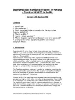
6 As a systems designer, you have under your direct control the receiver part of this landscape, and perhaps some portion of the path. But seldom will the designer have control over the actual source. EMI NOISE SOURCES. There are countless ways in which undesired noise can couple into an analog circuit to ruin its accuracy. Some of the many examples of these noise sources are listed in Figure 1. EMI/RFI noise sources can couple from anywhere Some common sources of externally generated noise: Radio and TV Broadcasts Mobile Radio Communications Cellular Telephones Vehicular Ignition Lightning Utility Power Lines Electric Motors Computers Garage Door Openers Telemetry Equipment Figure 1: Some Common EMI Noise Sources Since little control is possible over these sources of EMI, the next best management tool one can exercise over them is to recognize and understand the possible paths by which they couple into the equipment under design.
7 Page 2 of 16. MT-095. EMI COUPLING PATHS. The EMI coupling paths are actually very few in terms of basic number. Three very general paths are by: 1. Interference due to conduction (common-impedance). 2. Interference due to capacitive or inductive coupling (near-field interference). 3. ELECTROMAGNETIC radiation (far-field interference). NOISE COUPLING MECHANISMS. EMI energy may enter wherever there is an impedance mismatch or discontinuity in a system. In general this occurs at the interface where cables carrying sensitive analog signals are connected to PC boards, and through power supply leads. Improperly connected cables or poor supply filtering schemes are often perfect conduits for interference.
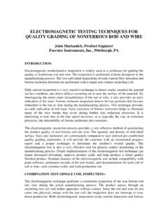
8 Conducted noise may also be encountered when two or more currents share a common path (impedance). This common path is often a high impedance "ground" connection. If two circuits share this path, noise currents from one will produce noise voltages in the other. Steps may be taken to identify potential sources of this interference (see References 1 and 2, plus tutorial MT- 031). Figure 2 shows some of the general ways noise can enter a circuit from external sources. Impedance mismatches and discontinuities Common-mode impedance mismatches Differential Signals Capacitively Coupled (Electric Field Interference). dV/dt Mutual Capacitance Noise Current (Example: 1V/ns produces 1mA/pF).
9 Inductively Coupled (Magnetic Field). di/dt Mutual Inductance Noise Voltage (Example: 1mA/ns produces 1mV/nH). Figure 2: How EMI finds Paths into Equipment There is a capacitance between any two conductors separated by a dielectric (air and vacuum are dielectrics, as well as all solid or liquid insulators). If there is a change of voltage on one conductor there will be change of charge on the other, and a displacement current will flow in the dielectric. Where either the capacitance or the dV/dT is high, noise is easily coupled. For example, a 1-V/ns rate-of-change gives rise to displacement currents of 1 mA/pF. If changing magnetic flux from current flowing in one circuit couples into another circuit, it will induce an emf in the second circuit.
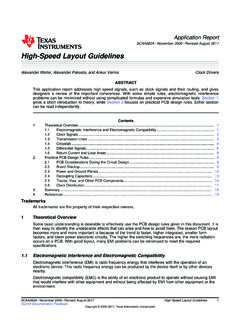
10 Such mutual inductance can be a troublesome source of noise coupling from circuits with high values of dI/dT. As an example, a mutual inductance of 1. nH and a changing current of 1 A/ns will induce an emf of 1 V. Page 3 of 16. MT-095. REDUCING COMMON-IMPEDANCE NOISE. Steps to be taken to eliminate or reduce noise due to the conduction path sharing of impedances, or common-impedance noise are outlined in Figure 3. Common-impedance noise Decouple op amp power leads at LF and HF. Reduce common-impedance Eliminate shared paths Techniques Low impedance electrolytic (LF) and local low inductance (HF) bypasses Use ground and power planes Optimize system design Figure 3: Some Solutions to Common-Impedance Noise These methods should be applied in conjunction with all of the related techniques discussed in tutorial MT-031.