Transcription of High-Speed Layout Guidelines - Texas Instruments
1 1 SCAA082A November2006 RevisedAugust2017 SubmitDocumentationFeedbackCopyright 2006 2017,TexasInstrumentsIncorporatedHigh-Sp eedLayoutGuidelinesApplicationReportSCAA 082A November2006 RevisedAugust2017 high -SpeedLayoutGuidelinesAlexanderWeile r,AlexanderPakosta,and ,suchas clocksignalsand theirrouting,and givesdesignersa reviewof the ,electromagneticinterferenceproblemscan be minimizedwithoutusingcomplicatedformulas and shortintroductionto theory,whileSection2 focuseson be ,Vias,and trademarksare the propertyof desirableto effectivelyuse the PCBdesignrulesgivenin this istheneasyto identifythe undesirableeffectsthat can ariseand how to reasonPCBlayoutbecomesmoreand moreimportantis becauseof the trendto faster,higherintegrated,smallerformfacto rs,and higherthe switchingfrequenciesare, the moreradiationoccurson a ,manyEMI problemscan be minimizedto meetthe ElectromagneticCompatibilityElectromagne ticinterference(EMI)is radiofrequencyenergythat interfereswith the operationof radiofrequencyenergycan be producedby the deviceitselfor by (EMC)
2 Is the abilityof an electronicproductto operatewithoutcausingEMIthat wouldinterferewith otherequipmentand withoutbeingaffectedby EMI fromotherequipmentor November2006 RevisedAugust2017 SubmitDocumentationFeedbackCopyright 2006 2017,TexasInstrumentsIncorporatedHigh-Sp eedLayoutGuidelinesThe goal is to reduceEMI to meetthe requirementsgivenby the FederalCommunicationCommission(FCC)or the InternationalSpecialCommitteeon RadioInterference(CISPR)A basicEMI modelis shownin Figure1. Everydeviceacts as a sourceand simultaneouslyas a causeinterferencethrougha couplingpathand can be affectedby interferencethroughthe couplingcan be: Capacitive Inductive Galvanic RadiatedpowerFigure1.
3 Modelof ElectromagneticInterferenceThereis not just one couplingmechanismpresent,but rathera combinationof ,however,theseeffectscan be illustratesthe time and the frequencydomainof a ,it is a squarewave.,but inreality,it is not possibleto changefromlow levelto high level(andvice versa)in an to the rise and fall time,it has the shapeof a trapezoidin the time meansof the Fourierseries,the trapezoidconsistsof a seriesof sine and cosinesignalswith discretefrequencycomponentshavean envelopeas is shownin the lowerdiagramofFigure2. An importantaspectis that in the frequencydomainthe amplitudeof the higherfrequencyharmonicsdependson the rise and fall time of the longerthe rise time,the smallerthemagnitudeof the example,the harmonicsof a 100-MHzclocksignalare not negligible,especiallythe thirdand fifth.
4 In this case,considerationalso shouldbe madewith frequenciesup to CDCE906fromTexasInstruments,the usercan set differentrise and fall timesto reducethe amplitudeof the ,take careto ensurethesetimesdo not violatethe slewratespecificationsof the November2006 RevisedAugust2017 SubmitDocumentationFeedbackCopyright 2006 2017,TexasInstrumentsIncorporatedHigh-Sp eedLayoutGuidelinesFigure2. TimeDomainand FrequencyDomainof a the lengthsof tracesare in the rangeof the signal'swavelength,thenthe userhas to considertheeffectsof problemsthat a usermustdeal with are time delay,reflections, get a betterunderstandingof theseproblemsand whereand how they arise,it is usefultoknowwhattransmissionlinesare.
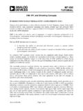
5 Theyare simplythe traceson a PCBand dependon the lengthand thefrequencyof the traceroutingare possibleon a commonstructuresare showninFigure3. On the left, a microstripstructureis illustrated,and on the right,a one reference,oftena groundplane,and theseare separatedby a striplinehastwo references,oftenmultiplegroundplanes,and are surroundedwith the Structureand Dimensionof Microstripand StriplineThe followingsectionsdescribesomeimportantpr opertiesof transmissionlineswhichare availableto calculatethe propertiesof the this applicationreport,the freewareAppCADfromAgilentis usedso that the readercanbecomefamiliarwith showsthe two structures,microstrip(top)and stripline(bottom).
6 The dimensions,the material,and the frequencyare in eachcaseshownon the left. The resultsthat are usedin the followingsectionscan be seenon the definesthe symbolsusedinFigure3 and +3 108m s eff November2006 RevisedAugust2017 SubmitDocumentationFeedbackCopyright 2006 2017,TexasInstrumentsIncorporatedHigh-Sp eedLayoutGuidelinesTable1. Descriptionof the SymbolsUsedin Figures3 and 4 SYMBOLDESCRIPTIONHH eightof the dielectricWWidthof the traceLLengthof the traceFrequencyThe frequencyon whichthe calculationsare basedZ0 Characteristicimpedanceof the WavelengthWavelength of the traceat the givenfrequencyand the giveneffectivedielectricVPVelocityof the signalon this tracewith the givendimensionsand frequencyrelativeto the speedof calculatedby VP.
7 Absolute= VP,.relative 3 108m/s effCombinationof the severaldielectricswhichsurroundsthe microstripW/HRatiobetweentracewidthand November2006 RevisedAugust2017 SubmitDocumentationFeedbackCopyright 2006 2017,TexasInstrumentsIncorporatedHigh-Sp eedLayoutGuidelinesFigure4. Calculationof Propertiesof Microstripand Stripline(AppCAD) +R*Z0R) + mm ns 100 mmV+3 108m s r November2006 RevisedAugust2017 SubmitDocumentationFeedbackCopyright 2006 2017, PropagationDelayTimeA signalcannotpassthrougha tracewith maximumspeedis the speedof light with 3 108m/s. For a certaintracelength,the signalneedsa certaintime to passit, and this is standardmediumfor the speedof light is air.
8 For anothermedium,thedielectricin a PCBenvironment,the speedis differentthanthat of the speedof light in air. The formulaforthe speedon a striplineis:(1)So, the speedis a functionof the dielectricwhichsurroundsthe a microstrip,it is morecomplicatedbecausethe traceis not surroundedby one at leasttwo: the substrateunderthe traceand the air abovethe the PCBcontainsa soldermask,a ,the calculationof an effective ris necessarybeforedeterminingthe the widthof the microstripand the distanceto the this case,the speedis afunctionof the presentdielectric,the tracewidth,and its distanceto the referenceplane[12].The signalspeedand the propagationdelaytime,respectively,on a signaltraceare importantwhen: Timingand skewrequirementsmustbe met (clockdistribution,buses,and so forth) Differentialtraceswereused(for example,LVDS) followingparametersare the samein eachcase:length= 100 mm;thickness= 35 m; height= mm; r= (FR4);frequency= 300 MHzIn Table2, the dependencyof signalspeedon the tracewidthat the microstripstructureis ,the signalspeedis not a functionof the sameis validfor the height.
9 (1)Pdis the propagationdelaytime in ps on the mentionedline with A Comparisonof PropagationDelayTimeWIDTH[mm] r,effVP,relativeVP,absolute[mm/ns]Pd(1)[ ps/100mm] ,Reflections,and TerminationAnotherpropertyof a transmissionline is the characteristicimpedance,Z0. The microstripin Figure4 hasfor the givenattributesa characteristicimpedanceZ0= 105 , and the striplineZ0= 55 . If thereare anyimpedancechangesin the signalchain(source trace vias connectors sink,and so forth), two extremeare a transmissionlinewith an openend (R = ) and a shortedend (R = 0 ). The reflectioncoefficient is the dimensionwhichexpressesthe relationshipbetweenthe impedanceof the transmissionline and the impedanceof thesourceor is calculatedasFor the two mentionedcases,the reflectioncoefficientbecomes = +1 for an openend and = 1 for a value1 meansthat the completesignalreflectsat this impedancechangeand goesbackto the avoidthis, the reflectioncoefficientmustbe = 0 to get no is the caseif the impedanceat the sourcehas thesamevalueas the characteristicimpedanceof the November2006 RevisedAugust2017 SubmitDocumentationFeedbackCopyright 2006 2017,TexasInstrumentsIncorporatedHigh-Sp eedLayoutGuidelinesIn Figure5.
10 The casewith an openend ( high -impedanceinputstageof the sink)is clocksourcehas an outputof V and an impedanceof 25 . The red line (dotted)is the idealshapeof greenone (dashed)is the real signalat the clock'soutputand the blue line is at the endof the transmissionline. The reflectionis the causeof theseover-and maximumvoltageat the traceend is V insteadof V, and the minimumvoltageis approximately 1 Vinsteadof 0 V. Thesecircumstancescan damagethe inputstageof the sourceand Over-and UndershootsDue to IncorrectTerminationA receiveroftenhas a avoidtheseover-and undershoots,the reflectionsmustbe ,a properterminationis mostcommonterminationtechniquesfollow: Seriestermination Paralleltermination Thevenintermination AC November2006 RevisedAugust2017 SubmitDocumentationFeedbackCopyright 2006 2017,TexasInstrumentsIncorporatedHigh-Sp eedLayoutGuidelinesEachof themhas advantagesand disadvantages,and the designerhas to tradeoff whichone is the bestsolutionfor his.