Transcription of Electron in a Magnetic Field - TAMUCC Physics Labs
1 Electron in a Magnetic Field Safety and Equipment 1. This lab involves high voltage. Do not touch the metal parts of the high voltage wires or connectors. The equipment should already be connected. If any connections come loose, turn off the power supplies and get the instructor s attention. 2. This lab involves a glass vacuum tube. If the glass cracks, it may rapidly implode sending glass flying. Do not touch the tube. Wear safety glasses. (Not necessarily chemical lab goggles) 3. e/m Apparatus (should be already set up) e/m apparatus, with glass vacuum tube and Helmholtz coils.
2 High-voltage power supply with low-voltage AC heater power supply. Low-voltage DC Power supply (may be part of high-voltage supply). Banana wires for connections. Introduction When an Electron accelerates through a potential difference, the potential energy of an Electron - Field system in converted into kinetic energy of the Electron . The potential difference that has accelerated the Electron could be used to calculate the velocity acquired by the Electron . If the accelerated Electron enters the Magnetic Field , this Magnetic Field will deflect it in a circular path (unless it is parallel the Electron s velocity).
3 The radius of the circular trajectory depends on the centripetal acceleration produced by the Magnetic force which, in turn is depends on both the velocity of the Electron and the magnitude of the Magnetic Field . The PASCO e/m Apparatus (Figure 1) consists of a vacuum tube in which a beam of electrons is accelerated by a potential difference to a certain speed. A pair of Helmholtz coils produces a uniform and measurable Magnetic Field perpendicular to the Electron beam. By measuring the accelerating potential (V), the current to the Helholtz coils (I), and the radius of the circular path of the Electron beam (r), the ratio e/m of the Electron will be calculated.
4 The socket of the vacuum tube does rotate, allowing the Electron beam to be oriented at any angle (from 0-90 degrees) with respect to the Magnetic Field from the Helmholtz coils to examine the vector nature of the Magnetic forces on moving charged particles. The Magnetic force (Fm) acting on a charged particle of charge q moving with velocity v in a Magnetic Field (B) is given by the equation: Fm = qvBsin . Since the Electron beam in this experiment is perpendicular to the Magnetic Field , the equation can be written as: = , where e is the charge of the Electron . Since the electrons are moving in a circle, this force is producing a centripetal acceleration of magnitude ac = 2.
5 Applying Newton s 2nd Law, 2 = or = (1) The kinetic energy acquired by the Electron equals work done by the electric Field that accelerated the Electron . Therefore eV = (1/2) mv2 or: = 2 / (2) The Magnetic Field produced near the axis of a pair of Helmholtz coils, B, is =(45)3/2 0 (3) (Yes, this looks a little like the solenoid formula, = 0 / . The radius is even the distance between the coils, which is like the length of a solenoid. The difference is that the Helmholtz coil has 2 loops overall. Also, with the Helmholtz coil, the coils are bunched up at the two ends, whereas with a solenoid they are spread out along the length of the solenoid.)
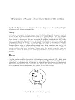
6 This reduces the Magnetic Field of the Helmholtz coil by a factor of (4/5)3/2 (Helmholtz coils are used because they allow a more open configuration and a more uniform Magnetic Field in the middle.) Notice that both, value of charge and value of mass of the Electron are still present in the expression for the velocity. Combining equation (1), (2), and (3) results in = =2 2 2=2 (5/4)3 2( 0 )2 (4) Where: V = the accelerating potential r = the radius of the Electron beam path R = the radius of the Helmholtz coils N = the number of turns on each Helmholtz coil = 130 0= the permeability constant = 4 x 10⁻⁷ I = the current through the Helmholtz coils Figure 1.
7 The e/m Apparatus, which includes some controls to adjust the Magnetic Field . Objective: To determine charge to mass ratio for an Electron . Data Collection and Analysis: 1. If you are working in a lighted room, place the hood over the e/m apparatus. 2. If you have the beige Uchida e/m Apparatus, check these settings for startup: Make sure the toggle switch is in the e/m MEASURE position. Turn the current adjust knob for the Helmholtz coils to the ON position. 3. On the power supplies, check these settings for startup: 500 V Adjust: all the way off (turned to left = CCW) AC Knob: 6 V 24 V DC Voltage Adjust: all the way off (turned to left = CCW) 24 V DC Current Adjust: DO NOT TOUCH 4.
8 Turn ON the power supplies. Wait a minute for the cathode to heat up. 5. Adjust the Accelerating Voltage on the electrodes to a value between 150V 200V until you see you will see the Electron beam emerge from the Electron gun. 6. Adjust the Voltage Adjust knob of the 24V Power Supply. Watch the ammeter and take care that the current does not exceed 2 A. This will curve the Electron beam by the Field from the Helmholtz coils. Helmholtz Coils Voltage: 8V DC DO NOT adjust Helmholtz Coils Current (on power supply) 7. Check that the Electron beam is parallel to the Helmholtz coils.
9 The beam should form a circle, not a spiral. If it is off, adjust the tube by turning the socket. Don t take tube out of its socket, the socket itself will turn. 8. Read the current to the Helmholtz coils from the 24 V power supply ammeter. Read the accelerating voltage from the 500 V power supply voltmeter. (The button switches between two ranges.) 9. Carefully measure the radius of the Electron beam. Look through the tube at the Electron beam. To avoid parallax errors, move your head to align the Electron beam with the reflection of the beam that you can see on the mirrored scale. Measure the radius of the beam as you see it on both sides of the scale, and then average the results.
10 10. Adjust the coil current and the accelerating voltage and take data for a second trial. Repeat this for a third trial. 11. Shutdown procedure: Turn down both voltage knobs (see Step 3 above), then turn off both power supplies. Description Trial 1 Trial 2 Trial 3 Measurements Helmholtz Coil I (A) Accelerating V (V) Beam Radius (m) Calculations e/m (C/kg) Average e/m (C/kg) Accepted Value e/m (C/kg) Difference % Error Table 1: Recorded data and calculation results for the e/m experiment. 12. For each trial, calculate the experimental value of the e/m ratio using equation (4) 13.