Transcription of 1. Semiconductor Materials & Physics
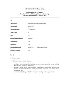
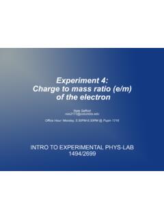
1 Chapter 1 1 CHAPTER 1: Semiconductor Materials & Physics In this chapter, the basic properties of semiconductors and microelectronic devices are discussed. Semiconductor Materials Solid-state Materials can be categorized into three classes - insulators, semiconductors , and conductors. As shown in Figure , the resistivity of semiconductors , , is typically between 10-2 and 108 -cm. The portion of the periodic table related to semiconductors is depicted in Table Figure : Typical range of conductivities for insulators, semiconductors , and conductors. semiconductors can be composed of a single element such as silicon and germanium or consist of two or more elements for compound semiconductors . A binary III-V Semiconductor is one comprising one element from Column III (such as gallium) and another element from Column V (for instance, arsenic).
2 The common element and compound semiconductors are displayed in Table Chapter 1 2 Table : Portion of the Periodic Table Related to semiconductors . Period Column II III IV V VI 2 B C N Boron Carbon Nitrogen 3 Mg Al Si P S Magnesium Aluminum Silicon Phosphorus Sulfur 4 Zn Ga Ge As Se Zinc Gallium Germanium Arsenic Selenium 5 Cd In Sn Sb Te Cadmium Indium Tin Antimony Tellurium 6 Hg Pd Mercury Lead Table : Element and compound semiconductors . Elements IV-IV III-V II-VI IV-VI Compounds Compounds Compounds Compounds Si SiC AlAs CdS PbS Ge SiGe AlSb CdSe PbTe SiCGe GaN CdTe GaAs ZnS GaP ZnSe GaSb ZnTe InAs ZnO InP InSb Chapter 1 3 Crystal Structure Most Semiconductor Materials are single crystals.
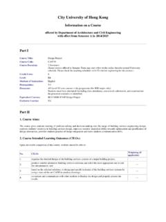
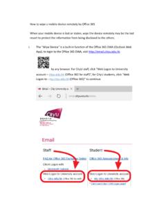
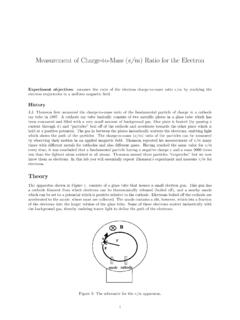
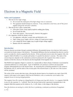
3 Figure exhibits three cubic-crystal unit cells - simple cubic, body-centered cubic, and face-centered cubic. The element semiconductors , silicon and germanium, have a diamond lattice structure as shown in Figure This configuration belongs to the cubic-crystal family and can be envisaged as two interpenetrating fcc sublattices with one sublattice staggered from the other by one quarter of the distance along a diagonal of the cube. All atoms are identical in a diamond lattice, and each atom in the diamond lattice is surrounded by four equidistant nearest neighbors that lie at the corners of a tetrahedron. Most of the III-V semiconductors ( GaAs) have a zincblende lattice (shown in Figure ) that is identical to a diamond lattice except that one fcc sublattice has Column III atoms (Ga) and the other has Column V atoms (As). Figure : Three cubic-crystal unit cells (a) Simple cubic (b) Body-centered cubic (c) Face-centered cubic.
4 Chapter 1 4 Figure : (a) Diamond lattice. (b) Zincblende lattice. Chapter 1 5 Energy Bands According to the Bohr model, the energy levels of a hydrogen atom are given by Equation : EmqhnneVHoo 422228136 . (Equation ) where mo denotes the free electron mass q denotes the electronic charge o denotes the free space permittivity h denotes the Plank constant n denotes the principal quantum number Therefore, for n = 1, that is, ground state, EH = eV. For n = 2, the first excited state, EH = eV. When two atoms approach one another, the energy level will split into two by the interaction between the atoms. When N atoms come together to form a crystal, the energy will be split into N separate but closely spaced levels, thereby resulting in an essentially continuous band of energy. The detailed energy band structures of crystalline solids can be calculated using quantum mechanics.
5 Figure is a schematic diagram of the formation of a diamond lattice crystal from isolated silicon atoms. The energy band splits into two, the conduction band and the valence band, as the two atoms approach the equilibrium interatomic spacing. The region separating the conduction and valence bands is termed the forbidden gap or bandgap, Eg. Figure exhibits the energy band diagrams of three classes of solids: insulators, semiconductors , and conductors. In insulators, the bandgap is relatively large and thermal energy or an applied electric field cannot raise the uppermost electron in the valence band to the conduction band. In metals or conductors, the conduction band is either partially filled or overlaps the valence band such that there is no bandgap and current can readily flow in these Materials . In semiconductors , the bandgap is smaller than that of insulators, and thermal energy can excite electrons to the conduction band.
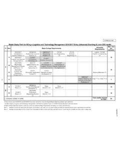
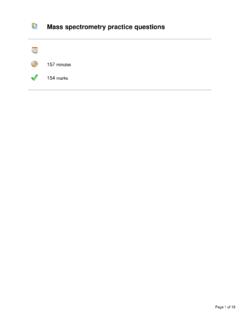
6 The bandgap of a Semiconductor decreases with higher temperature. For instance, for silicon, Eg is eV at room temperature and eV at zero Kelvin. Chapter 1 6 Figure : Formation of energy bands as a diamond lattice crystal by bringing together isolated silicon atoms. Figure : Schematic energy band representations of (a) an insulator, (b) a Semiconductor , and (c) conductors. Figure shows a more detailed schematic of the energy band structures for silicon and gallium arsenide in which the energy is plotted against the crystal momentum for two crystal directions. For silicon, the minimum of the conduction band and the maximum of the valence band have different crystal momenta. Silicon is therefore an indirect bandgap Semiconductor as a change in Chapter 1 7 crystal momentum is required for an electron transition between the valence and conduction bands.
7 On the contrary, GaAs is a direct bandgap Semiconductor and generation of photons is more efficient. Figure : Energy band structures of Si and GaAs. Circles (o) indicate holes in the valence bands and dots ( ) indicate electrons in the conductor bands. Chapter 1 8 Intrinsic Carrier Concentration The probability that an electronic state with energy E is occupied by an electron is given by the Fermi-Dirac distribution function: f(E) = kTEEFe/)(11 (Equation ) where EF is the Fermi level, the energy at which the probability of occupation by an electron is exactly one-half. At room temperature, the intrinsic Fermi level lies very close to the middle of the bandgap. The effective density of states in the conduction band NC is equal to 2[2 mnkT/h2]3/2. Similarly, the effective density of states in the valence band NV is 2[2 mpkT/h2]3/2. At room temperature, NC for silicon is x 1019 atoms/cm3.
8 For an intrinsic Semiconductor , the number of electrons per unit volume in the conduction band is equal to the number of holes per unit volume in the valence band. That is, n = p = ni where ni is the intrinsic carrier density. Since n = NCexp{-(EC-EF)/kT} and p = NVexp{-(EF-EV)/kT}, where n is the electron density and p is the hole density, np = ni2 = NCNVexp{(EV-EC)/kT} = NCNVexp{-Eg/kT}. Therefore, nNNEkTiCVg ()exp{}/122 (Equation ) For a doped, or extrinsic, Semiconductor , the increase of one type of carriers reduces the number of the other type. Thus, the product of the two types of carriers remains constant at a given temperature. For Si, ni = x 1010 cm-3 and for GaAs, ni = x 106 cm-3. GaAs has a lower intrinsic carrier density on account of its larger bandgap. (For derivation of the equations described in this section, please peruse the recommended textbooks.)
9 Chapter 1 9 Donors and Acceptors Figure shows schematically the doping of a silicon crystal with an arsenic atom. The arsenic atom forms covalent bonds with its four adjacent silicon atoms, and the fifth electron becomes a conduction electron , thereby giving rise to a positively charged arsenic atom. As a consequence, the silicon crystal becomes n-type and arsenic is called a donor. Boron, on the other hand, has only three outer shell electrons and is an acceptor in silicon. Impurities such as arsenic and boron have energy levels very close to the conduction band and valence band, respectively, as indicated in Figure Shallow donors or acceptors such as these exist in ionized form at room temperature because thermal energy is sufficient to ionize them. This condition is called complete ionization, that is, n = NA or ND.
10 Since n = NCexp{-(EC-EF)/kT}, ND = NCexp{-(EC-EF)/kT} and EC - EF = kT ln[NC/ND] (Equation ) One of the implications of Equation is that (EC-EF) becomes smaller with increasing ND, or in other words, the Fermi level moves closer to the bottom of the conduction band. Similarly, for p-type semiconductors , the Fermi level moves towards the top of the valence band with increasing acceptor concentration. When both donors and acceptors are present simultaneously, the impurity present at a higher concentration determines the type of conductivity in the Semiconductor . The electron in an n-type Semiconductor is called the majority carrier, whereas the hole in n-type Semiconductor is termed the minority carrier. Conversely, in a p-type Semiconductor , holes are majority carriers and electrons are minority carriers.