Transcription of ELECTRON SPIN RESONANCE - Physics & Astronomy
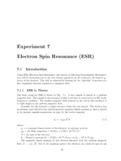
1 ELECTRON SPIN RESONANCE . Last Revised: July 2007. QUESTION TO BE INVESTIGATED. How can we measure the Land g factor for the free ELECTRON in DPPH as predicted by quantum mechanics? INTRODUCTION. ELECTRON spin RESONANCE (ESR) is a useful tool for investigating the energy absorption spectra of many materials with unpaired electrons ( paramagnetic materials). In this lab exercise you will explore the absorption of a paramagnetic molecule. A paramagnetic material has an electronic structure that leaves an ELECTRON in a state such that it does not have a partner of opposite spin.
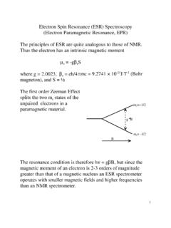
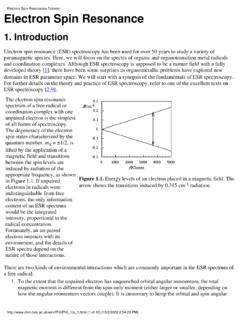
2 This implies that the molecule will have an intrinsic magnetic dipole moment. This experiment will allow you to verify the quantum mechanical model used to describe the paramagnetic system. You will be able to observe the absorption behavior of the ELECTRON , as well as determine the Land g factor associated with this system. THEORY. ESR is a purely quantum mechanical effect. It relates the interaction of an external magnetic field to an ELECTRON 's magnetic moment, which is a result of its intrinsic spin. Since the spin of an ELECTRON may either be up or down, so may its magnetic moment.
3 This implies that, in the presence of an external magnetic field, one spin state will be higher in energy than the other. More specifically, the spin with a moment pointing in the direction of the external field is lowest in energy. These states have an energy E, as either (1). Where g is the Lande' factor, B is the Bohr magneton (a constant), and B is the value of the external magnetic field. Thus, the change in energy from the negative to the positive spin state can be written (2). Therefore, because g and B are constants, there are pairs of values of the energy E and of the external field B that satisfy Eq.
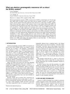
4 (2) and result in a transition of spin states. At commonly attainable magnetic field strengths the corresponding energy lies in the radio-frequency (RF) regime. Where the general expression for the energy of a photon applies (3). Where E is the energy of an RF photon, h is Plank's constant, and is the frequency of the photon. When a photon of energy E is incident on an ELECTRON in a field of strength B ELECTRON RESONANCE will be observed. EXPERIMENT. The electrons that you will manipulate are located in the paramagnetic molecule Diphenyl-Picryl-Hydrazyl (DPPH). DPPH is pictured below; notice the unpaired ELECTRON .
5 This ELECTRON is also very weakly bound to the nitrogen atom. The combination of these two properties makes this molecule ideal for studying the magnetic properties of the ELECTRON . The DPPH has been loaded onto a piece of cotton and placed inside of a sample tube. The sample tube should then be placed in a coil and inserted into the mount (light grey cylinder in Figure 2). Consult the manufacturer's manual for any necessary information concerning the setup of this device. Figure 1. Sketch of the structure of a DPPH. molecule showing the nitrogen (N) contributing the free ELECTRON .
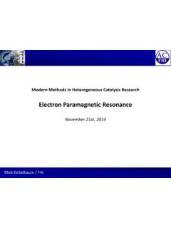
6 Figure 2 shows a block diagram depicting the experimental setup. There are essentially two circuits: The first controls and monitors the RF signal driving of the electrons (at left), and the second controls the external magnetic field (right). You should observe the output of the absorption of the DPPH on one channel of the oscilloscope (DC couple the o-scope channel) and the voltage across the resistor on Figure 2. A drawing of the basic elements of the experiment is shown. The circuit is also shown. the other channel. The frequency of the RF input can be selected by a knob located on the top of the sample-mount box.
7 This box also contains a bridge circuit to amplify the absorption signal and cancel out the electronics RESONANCE effects. The second circuit controls the current running through the Helmholtz coils, and consequently the external magnetic field. A special voltage source is to be used which applies a ramped signal with a long period. This signal is one-half of a triangle wave, whose frequency, sign, and amplitude you may adjust. You should observe the half triangle on the remaining oscilloscope channel by monitoring the voltage drop across the 1 resistor in this circuit (see Figure 2).
8 Observing these two signals will allow you to correlate the occurrence of RESONANCE to the value of the external B. field. The purpose of the resistor is to limit the current in the circuit and allow you to observe the signal on the oscilloscope. A measurement of the resistor's value and the oscilloscope trace will allow you to calculate the current in the coils at any given time. As the voltage increases from the triangular current source so does the current running through the coils, which in turn creates the desired magnetic field around the sample. At a specific value of this field (see Eq.)
9 2) RESONANCE will occur and you will see a very obvious dip in the output of the RF device. You will see two symmetrical dips, one as the B field ramps up through the value specified by Eq. 2 and another as it descends through this same value. These dips occur because the electrons are absorbing some of the photons. If you ramp the field too quickly the peaks will not be symmetric. Can you explain why this happens? Choose a repetition rate and ramping period such that the entire shape of the RESONANCE is seen during the ramps. It may take some practice to achieve the right shape and repetition rate for the ramp.
10 A uniform magnetic field can be reasonably achieved using Helmholtz coils. Helmholtz coils are composed of two coaxial coils of wire separated by a distance equal to their radii. A derivation of the field from two coils in the Helmholtz configuration is in the Appendix. Each coil should have the same number of windings and the same radius. The coils should also have the same current running through them (wired in series, Figure 2). When all of these conditions are met there will be a volume of nearly uniform field within the coils. Use the Gaussmeter to prove that the field is uniform over the length of the sample.