Transcription of Electronic Proportional (EP) Control for Medium …
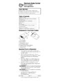
1 Electronic Proportional (EP) Control for Medium Duty 72400 Piston Pumps The Electronic Proportional (EP) Control is ideal for a wide range of mobile and industrial applications where electrical Control of pump displacement is desired. Eaton's robust design incorporates an Electronic module, Proportional solenoids and a valve assembly. Pump displacement is controlled by an input command signal which is converted into Proportional current output by the Electronic module. The Proportional solenoid-actuated valve assembly then converts the current output into Proportional pump displacement. Designed to meet the rigorous duty cycle requirements of off- highway equipment, the EP Control utilizes an Electronic module encapsulated in an aluminum enclosure and environmentally-sealed Metri-Pack connectors to assure maximum protection from the elements.
2 The EP Control is designed to resist Electromagnetic Interference (EMI) which could affect proper operation. The EP Control offers maximum design and application flexibility with two different types of command input options and compatibility with both 12 and 24 Vdc power supplies. Typical input devices include joysticks (1-6 Vdc) and PLCs ( 4-20 mA). For precise, repeatable operation, closed-loop current Control is used to compensate for resistance and voltage changes of the Proportional solenoids due to temperature variation. In the event of a power loss or loss of signal, the EP Control automatically returns the pump to neutral. Mechanical feedback of the swashplate position provides closed-loop Control to maintain the selected displacement setting over a wide range of operating conditions.
3 Solenoids have integral manual override actuators. EP Control Features Electronic Module Qualification (Contact Eaton for Specific Levels). Robust, flexible Electronic pump Control Electronic module encapsulated for environmental protection SAE J1455 - Recommended Environmental Practices for Electronic Equipment Design Automotive style environmentally sealed Metri-Pack connectors . Humidity/Temperature Extreme Cycling Closed-loop current Control compensates for resistance change of the Proportional solenoids due to temperature variations Salt Spray Return to neutral for loss of power or loss of command input Splash & Immersion signal Steam Cleaning/High Pressure Wash Mechanical feedback of swashplate position for closed-loop Vibration Control Mechanical Shock Two choices for command input signal Temperature Cycling Operates from 12 or 24 Vdc power supply Load Dump Transients Ease of installation Inductive Load Switching Transients Operating temperature range -40 to +85 C.
4 SAE J1113 - Electromagnetic Susceptibility Measurement On-pump mounting for many installations Procedures for Vehicle Components External neutral adjustment EMI/EMC - Conducted & Radiated Immunity Manual override capability CISPR 25 - International Electrotechnical Commission Limits and Drive module qualification per SAE J1455, SAE J1113, CISPR 25 Methods of Measurement of Radio Disturbance Characteristics External fuse (customer supplied): 3A for the Protection of Receivers used on Board Vehicles . EMI/EMC - Conducted & Radiated Emissions Electronic Proportional (EP) Control For Medium Duty 72400 Piston Pumps Model Code MODEL CODE DESCRIPTION. NOMINAL COMMAND.
5 INPUT IMPEDANCE OF. Position 16,17 MODEL CODE COMMAND INPUT SIGNAL TYPICAL INPUT DEVICES Electronic MODULE. Joysticks or potentiometers with a resistance EE 1 to 6 Vdc Potentiometric between 160 ohms and 50K ohms 500K Ohms EG 4-20 mA Current Loop Programmable Logic Controllers (PLC) 250 Ohms EC 12 Volts Requires customer supplied electronics ED 24 Volts Requires customer supplied electronics Interconnect POWER. SUPPLY. Schematic CONNECTOR Solenoid (2-Pin) Connector see chart A. A+. On/Off Switch B. B- + - C. FUSE D. Battery or Electronic Power Supply Module Proportional Customer Solenoid 1. Supplied Components A Servo Orifices Valve Supply Orifice (Optional) Assembly (Optional).
6 B. S1 P. C. S2. COMMAND. INPUT SIGNAL. CONNECTOR. (3-Pin). see chart Mechanical Proportional Swashplate Solenoid 2 Feedback Command Input Signal Connector Power Supply Connector COMMAND INPUT SIGNAL PINS WIRE COLOR SIGNAL PINS WIRE COLOR SIGNAL. A Black Ref Low - 1 Vdc A Red + Supply Voltage 1 to 6 Vdc Potentiometric B Green Command (wiper) B Black Supply Return C Red Ref Hi - 6 Vdc A Orange Loop Return 4-20 mA Current Loop B White Loop In Fuse Rating C No Connection Required*. *EP Control Electronic Module Mating Connector Kit 990762-000 contains plug 3 Amp SLO-BLO (Time Delay) fuse for used to seal mating end connector. 12-24 Vdc system - customer supplied 2 EATON EP Control for Medium Duty 72400 Piston Pumps Data Sheet E-PUPI-MS002-E September 2002.
7 Valve Assembly Proportional S1 P S2 Feedback Link Proportional Solenoid 1 Solenoid 2. Installation Front mounting flange surface 73,7. [ ] 112,6. [ ] 131,3. [ ]. 165,1. [ ]. Neutral Adjustment 139,6 154,9. [ ] [ ] Power Supply Command Input Signal 167,2. [ ]. 90,7 Proportional Proportional [ ] Solenoid 2 Solenoid 1. Centerline of drive shaft 2X Manual Overide, Push to activate manual override. EP Control Connector Kits Electronic Module Mating Connector Kit Solenoid Coil Mating Connector Kit KIT NO. PART (QTY.) DELPHI PACKARD P/N (not needed when using an Eaton Electronic Module). KIT NO. PART (QTY.) DELPHI PACKARD P/N. 990762-000 Command Input Signal Connector (1) 1211 0293.
8 Terminal (3) 1204 8074 9900023-000 Connector (1) 1218 6568. Cable Seal (3) 1204 8086 Terminal (4) 1204 8074. Cavity Plug (1) 1205 9168 Cable Seal (4) 1204 8086. Secondary Lock (1) 1205 2845 Secondary Lock (1) 1204 7948. Power Supply Connector (1) 1205 2641 Recommended wire size: 16 - 18 AWG. Recommended cable diameter: - mm Terminal (2) 1204 8074 Alternate reference source: Pioneer Standard Electronics 1-800-257-6613. Cable Seal (2) 1204 8086 Secondary Lock (1) 1205 2634. Recommended wire size: 16 - 18 AWG Solenoid Connector Update Kit Recommended cable diameter: - mm Note:This kit was created to update electrical connectors, on field units, to the current design.
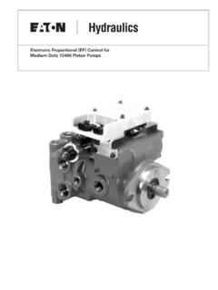
9 It is to Alternate reference source: Pioneer Standard Electronics 1-800-257-6613 be used when replacing solenoid coils, with the previous-design connectors, with new coils with new- style connectors. The kit contains necessary parts and a tool to update the connector that mates the new solenoid coil connector. KIT NO. PART (QTY.) DELPHI PACKARD P/N. 9900045-000 Tool (1) 1209 4429. 4-Pin Housing Connector (Female) (1) 1218 6568. 4-Pin Housing Connector (Male) (1) 1218 6271. EATON EP Control for Medium Duty 72400 Piston Pumps Data Sheet E-PUPI-MS002-E September 2002 3. Pump Displacement Full Stroke Port B Flow*. A. (MAX). B. (MIN). C D. (MIN). E. (MAX).
10 Vs. Input Signal Command Input Signal 1-6 Vdc Vdc Vdc Vdc Vdc Vdc 4-20 mA -20 mA mA 0 mA + mA +20 mA. Shaft Rotation CCW Solenoid #2 Neither Solenoid #1. Minimum Neutral Range Flow OUT port B No flow Flow OUT port A . A CW Solenoid #2 Neither Solenoid #1. B C D E Flow OUT port A No Flow Flow OUT port B . Note: The +20 mA command input signal configuration *Note: Actual flow direction depends operates the pump in one direction. The customer has to Full Stroke Port A Flow* on pump type and rotation change the polarity on the -20 mA signal to operate the pump in the opposite direction. Typical Control Characteristics EP Control KIT NO. MODEL. CODE REF. KIT DESCRIPTION.